HandiQuilter.com
Page 17
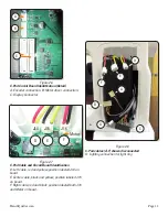
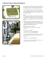
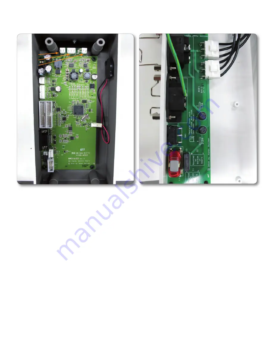
Figure 2.18
Inside View of C-Pod
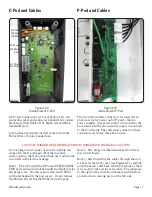
C-Pod and Cables
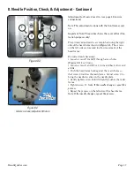
P-Pod and Cables
Figure 2.19
Inside View of P-Pod
Do not plug in main power or run the quilting ma-
chine with the P-pod taken off of the machine
and/or open so that any human body part could come
in contact with electrical energy.
Note 1: The C-Pod and the P-Pod are STATIC SENSI-
TIVE parts and should not be handled without special
discharge tools. For this reason, all C and P Prints
will be exchanged in the pod covers. Do not remove
the Printed Circuit Boards (PCBs) from the pods.
Note 2: The plugs are labeled and keyed on the C-
pod circuit board.
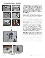
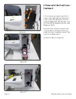
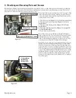
Note 3: After installing the cables through the serv-
ice hole on the front cover (see
Figure 2.7
), carefully
push the excess cable back into the machine as there
is no room in the pod for extra cable. The cables are
to the right of the drive-train bracket and therefore
protected from moving parts on the left side.
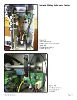
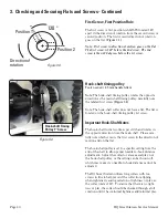
DC Power Connections (at top of photo): Left, red
and yellow cable and connector (labeled J14). Center,
black and yellow (labled J15). Right, red and black
(labeled Motor).
Control Board Connections (left center): Encoder,
Motor Driver, Display Connections.
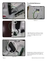
The two bottom white connectors (at lower left in
photo) are for AC power out of P-pod to the two
power supplies. One power supply is mounted to the
back frame and the second power supply is mounted
to the front frame. The cables that connect to these
connectors each have three black wires.
CAUTION
! DANGER OF ELECTRICAL SHOCK! DANGEROUS VOLTAGES.
CAUTION
!
J14 Power
J15 Power
J16 Motor
J13 Motor
Driver
J11 Display
J12 Display
J8 Encoder