
HandiQuilter.com
Page 37
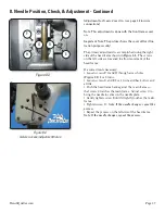
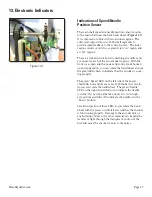
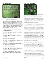
13. Electronic Indicators
The main shaft speed and needle position sensor mounts
to the main shaft near the back hand wheel. (
Figure 13.1
)
It is composed of a disk with two encoder regions. The
outermost region consists of 100 small segments to
provide speed feedback to the control system. The inner
region consists of only two segments (an “on” region and
an “off” region).
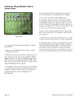
There is a forked circuit board containing an emitter and
a receiver for each of the two encoder regions. With the
front cover open and the power and control pods hooked
up and powered on, you can rotate the hand wheel and see
the green LEDs fl ash to indicate that the encoder is work-
ing properly.
The green “Speed” LED on the left side of the board
should fl ash on and off at a rate of 100 fl ashes per revolu-
tion as you rotate the hand wheel. The green “Needle”
LED on the right should turn on to indicate the needle
is in the “Up” position (the take-up lever is in its high-
est position) and turn off to indicate the needle is in the
“Down” position.
Careful inspection of these LEDs as you rotate the hand
wheel with the power on will tell you whether the encoder
is functioning properly. Damage to the encoder disk or
any build-up of dust, oil or other material can impede the
transfer of light through the transparent portion of the
disk and cause the encoder to miss some pulses.
Figure 13.1
Indications of Speed/Needle
Position Sensor


