GB
77
1622
582
23
00
G 90
Combustible roof
Combustion air hose
(accessory)
4
42
E 150
A 1116
1435*
B 1033
F 410
1532*
C 188
D 85
502
462
Utv. Ø150
28
8
100
600
890
500
400
300
200
3
00
4
00
5
00
200
Combustible wall
Permitted area for
combustible material
435
120
89
0
810
Combustible wall
H26T/K High
* Used when installing optional baking oven
** To prevent discolouration of painted firewalls, we recommended the same side distance as to combustible walls.
23
8
5
0
300**
590
Fire-retardant wall of
brick or concrete
3
65
5
0
795
74
0
Fire-retardant wall of
brick or concrete
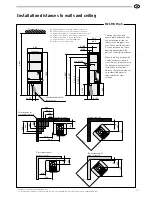
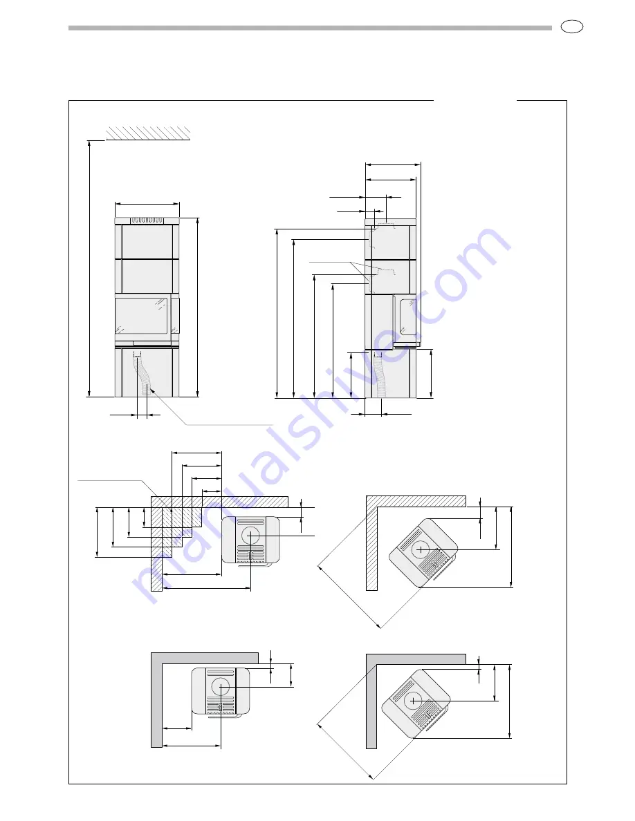
A = height from floor to upward chimney connection
B = height from floor to c/c rear chimney connection
C = distance from back to c/c upward chimney connection
D = distance from back to rear chimney connection
E = distance from back to hole in base plate
F = height from floor to air inlet (410 mm)
G = distance to hole in base plate
Position the stove on a
hearth plate and check that
the installation distances
shown in the diagrams are
met. There must be at least
1 metre between the stove
opening and combustible
parts of the building or décor.
When installing a stove with
a top flue connection to a
steel chimney, please refer to
the relevant manufacturer’s
installation instructions.
Observe the safety distances
to combustible material
required for the steel
chimney.
Installation distances to walls and ceiling


