


-20-
PREPARING FOR OPERATION
Tractor Hitch
ATTENTION:
Remove tractor quick coupler (If equipped). Tractor three point arms should be removed
or positioned so they cannot come in contact with spreader.
Failure to heed will cause damage to
spreader and Void Warranty.
Fasten the spreader hitch to the drawbar with a
hitch pin with a
safety locking device.
Use 1-1/2”
diameter hitch pin to pull spreader. Remove the weight from the jack (jack is not to be used when spreader
is loaded). Remove jack from pipe mount and place on convenient storage mount located on the side of
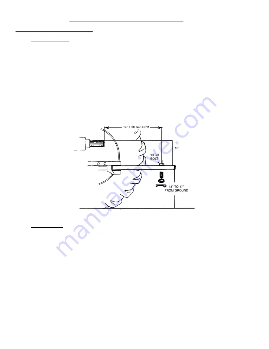
the left push frame brace. This allows protection of jack from tractor tires during turns. The hitch of the
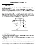
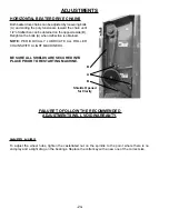
spreader is designed for a standardized tractor hitch. Adjust the drawbar so that it is 13 to 17 inches above
the ground. Extend or shorten it so that the horizontal distance from the end of the tractor power takeoff
shaft to the center of the hitch pin hole is 14 inches for 540 PTO and 15-3/4” for 1000 PTO as shown in
drawing. An improperly located hitch point may cause damage to the universal joints of the power takeoff.
Secure the drawbar so that the hitch pin hole is directly below the power drive line.
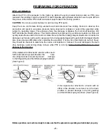
TRACTOR CONNECTIONS
15-3/4” for 1000 RPM
Hydraulics
The spreader requires a 4-hose hook-up;
1. Connect the set of hydraulic hoses which operate the Manure Spreader hydraulic push gate from the
spreader to a double acting valve on the tractor.
2. Connect the set of hydraulic hoses which operate the hydraulic endgate to another double acting valve
on the tractor.
3. The hydraulic endgate must be raised completely prior to activating hydraulics for pusher.
4. Operate the tractor valve to fill the hydraulic lines and operate the cylinders. Add hydraulic fluid to the
tractor system, as required.
Note: Before operation, run the machine slowly to make sure that the Manure Spreader is operating
and lubricated properly.
Summary of Contents for 4242
Page 6: ...4 Intentionally Left Blank...
Page 8: ...6 Intentionally Left Blank...
Page 10: ...8 Intentionally Left Blank...
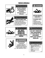
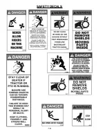
Page 13: ...11 SAFETY DECALS...
Page 14: ...12 SAFETY DECALS...
Page 15: ...13 SAFETY DECALS...
Page 18: ...16 HYDRAULIC FITTING TORQUE SPECIFICATIONS...
Page 19: ...17 HYDRAULIC FITTING TORQUE SPECIFICATIONS...
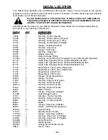
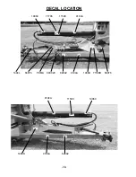
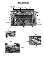
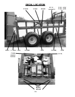
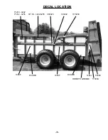
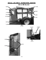
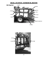
Page 38: ...36 DECAL LOCATION 425 Bushel DCRED 093020 093020 111593A 1494J 86060 DCAMB...
Page 41: ......


