background image

-27-

LUBRICATION GUIDE

GREASING

There are numerous grease fittings on the spreader. If these are lubricated properly and often enough, 

it will prolong the life of the spreader. (Grease every 20 hours, 

also before and after power washing.

Make certain that the grease fittings are free of paint and dirt, force a high-quality grease into them until 

the grease comes out around the shaft on the sleeve-type bearings. On the sealed ball bearings, grease 

should be added slowly until a slight bead forms at the seals indicating the correct amount of lubricant.

Wipe off excess grease to prevent the accumulation of chaff and grit around the bearings. 

GENERAL INFORMATION

IMPORTANT: 

Catch and dispose of fluid per local waste disposal regulations whenever service is performed 

on hydraulic components, valves, cylinders, hoses, etc.

The  operator  should  become  familiar  with  all  lubrication  points  and  establish  a  systematic  routine                         

to ensure complete and quick lubrication of the machine.
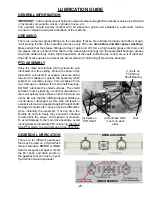
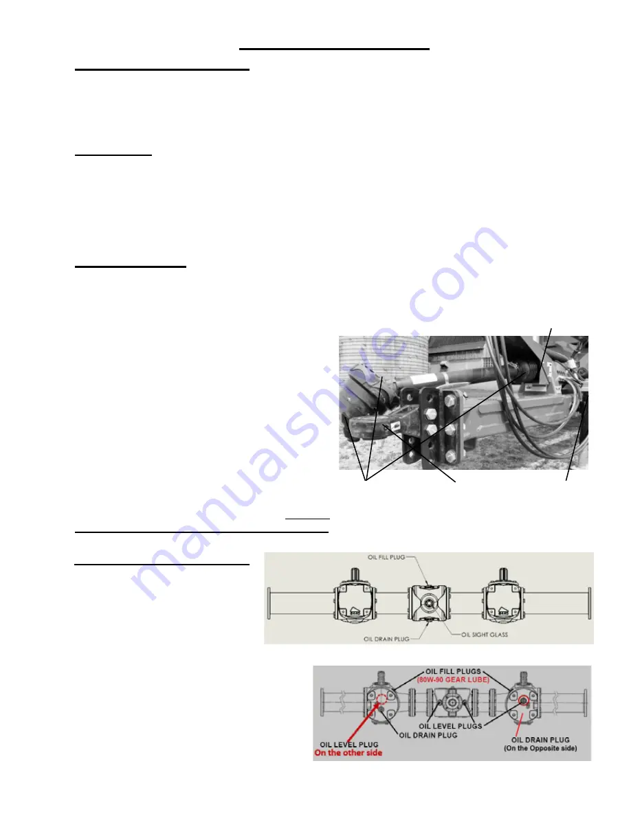
PTO ASSEMBLY

Keep the male and female driving elements well 

lubricated  and  free  sliding.  Failure  to  observe  this          

precaution will result in excessive pressure being 

required to collapse or extend the assembly while 

subject to  operating torque. This excessive force 

may damage or displace the main shaft bearings. 

DO NOT lubricate the shield surfaces. The shield 

surfaces must be kept dry, as dirt accumulation on 

them will quickly cause these units to bind and not 

rotate. Be sure that the rotating integral shields are 

not dented or damaged, as this also will result in 

excessive force being applied against the jackshaft. 

Damaged  shields  also  cause  obvious  difficulties 

when installing the assembly. If at any time the 

shields do not turn freely, they should be checked 

to determine the cause, and repaired or cleaned. 

To avoid damage to the main drive bearings, avoid 

turning sharp corners while PTO is running. Start and 

Stop PTO slowly to avoid damage to the drive line.
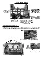
(3) Zerks on

PTO Shaft

(1) Zerk on 

Front Drive 

Shaft Bearing

Jack

(2) Bullnose Hitch 

(1 zerk on each 

side)

GEARBOX LUBRICATION

There  are  (2)  different  gearboxes 

that may be used on a Hydra-Push 

manure spreader; BERMA or OMNI. 

See the respective images to locate 

the fill, check, and drain points on 

the gearbox that you have on your 

Hydra-Push manure spreader. 

BERMA GEARBOX

OMNI GEARBOX

Summary of Contents for 4242

Page 1: ...322VP55020 HPV4255 Starting Ser 322VP55020 HPH4255 Starting Ser 322HP55002 HPH4255 Starting Ser 322HP55002 Part 89980 Rev 01 HSMFG0223 Part 89980 Rev 01 HSMFG0223 READ AND UNDERSTAND THIS MANUAL BEFO...

Page 2: ...fety Signs 10 Safety Decals 11 13 Safety Information Warning Owner Must Read and Understand 14 Cap Screw Torque Values 15 Hydraulic Torque Specs 16 17 Set Up Assembly 18 Transporting 19 Preparing for...

Page 3: ...ded solely to the original purchaser of the product is terminated upon any subsequent transfer or sale from or by the original purchaser and extends no third party benefits or rights whatsoever The wa...

Page 4: ...NT Congratulations on your selection of an H S product Your new H S product has been manufactured of the finest quality materials and components The performance you receive from your machine is largel...

Page 5: ..._________________________________ Serial Number __________________________________________________ You have received the Operator s Manual for this product Yes _____ No _____ Interested in receiving t...

Page 6: ...4 Intentionally Left Blank...

Page 7: ...FOR RECORDS After the Manure Spreader has been completely set up check to be certain it is in correct operating order before delivering to the customer The following is a list of points to inspect Ch...

Page 8: ...6 Intentionally Left Blank...

Page 9: ...hen operating this unit Explain recommended loads for different types of materials Explain to customer that regular lubrication is required for proper operation and long life of machine Show customer...

Page 10: ...8 Intentionally Left Blank...

Page 11: ...EVER YOUR PERSONAL SAFETY IS INVOLVED TAKE TIME TO BE CAREFUL REMEMBER THE CAREFUL OPERATOR IS THE BEST OPERATOR MOST ACCIDENTS ARE CAUSED BY HUMAN ERROR CERTAIN PRECAUTIONS MUST BE OBSERVED TO PREVEN...

Page 12: ...s in good condition Immediately replace any missing or damaged signs OBSERVE MAXIMUM TRANSPORT SPEED The maximum transport speed for this implement is 32 km h 20 mph Some tractors are capable of opera...

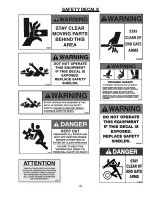
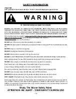
Page 13: ...11 SAFETY DECALS...

Page 14: ...12 SAFETY DECALS...

Page 15: ...13 SAFETY DECALS...

Page 16: ...LIFIED OPERATOR NEAR THE MACHINE Before starting tractor be sure PTO shields turn freely and PTO is securely locked to tractor DO NOT clean adjust or lubricate the machine when any part is in operatio...

Page 17: ...Dry Ft Lbs Lube Ft Lbs Inch Lbs Inch Lbs Inch Lbs Inch Lbs 1 4 20 1 4 28 5 5 6 3 4 2 4 7 8 10 6 3 7 2 12 14 9 10 75 2 94 0 78 8 99 0 61 5 77 0 68 6 87 0 5 16 20 5 16 28 11 12 8 9 17 19 13 14 24 27 18...

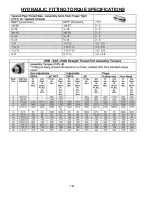
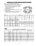
Page 18: ...16 HYDRAULIC FITTING TORQUE SPECIFICATIONS...

Page 19: ...17 HYDRAULIC FITTING TORQUE SPECIFICATIONS...

Page 20: ...assembly and adjustment and make sure that all bolts are tightened 4 Securely retighten after a few hours of operation as bolts can loosen up on new machinery 5 Lubricate the machine completely check...

Page 21: ...garding use of a safety chain and transport lighting when towing farm equipment on public highways A proper safety chain should be used to retain the safety connection between the towing and towed mac...

Page 22: ...from the end of the tractor power takeoff shaft to the center of the hitch pin hole is 14 inches for 540 PTO and 15 3 4 for 1000 PTO as shown in drawing An improperly located hitch point may cause da...

Page 23: ...surfaces The shield surfaces must be kept dry as dirt accumulation on them will quickly cause these units to bind and not rotate Be sure that the rotating integral shields are not dented or damaged as...

Page 24: ...MUST BE RAISED COMPLETELY prior to engaging hydraulic pushgate 3 Engage the tractor hydraulic lever into the detent position to operate the spreader hydraulic pusher 4 The spreader pusher hydraulic h...

Page 25: ...ation is normally due to large frozen chunks of manure foreign objects rocks chunks of wood etc in the manure running the spreader push gate too fast when unloading long straw and pen packed material...

Page 26: ...obtained Shields Opened for Clarity BE SURE ALL SHIELDS ARE SECURED INTO PLACE PRIOR TO RESTARTING MACHINE WHEEL HUBS To adjust the wheel hubs tighten the castellated nut on the spindle to the point...

Page 27: ...front portion of the PTO from the shaft 4 After removal of both PTO halves slide them together and store them in a safe place 5 Securely attach a lifting chain to the lifting eyes at the top of the be...

Page 28: ...cal beater models to protect you and the tractor from any flying material when turning a corner MANUAL ADJUST HYDRAULIC VARIABLE SPEED PUSHER CONTROL The optional manual adjust valve allows you to adj...

Page 29: ...ding Failure to observe this precaution will result in excessive pressure being required to collapse or extend the assembly while subject to operating torque This excessive force may damage or displac...

Page 30: ...n the end of each Beater The R H zerks are under the shield 2 Zerks on Overrunning Clutch HB model Zerk Behind Shield on bearing 1 Zerk on each hub on all wheels 2 Remote zerks for the main drive shaf...

Page 31: ...ing Do Not Remove Shields Only on Vertical Beater Spreader 67130 1 Hydra Push Spreader Decal HP4242 HP4255 Left Side 67131 1 Hydra Push Spreader Decal HP4242 HP4255 Right Side 67132 1 Hydra Push Sprea...

Page 32: ...30 DECAL LOCATION 1906D 9194A 9194A 11599 1906C 82602 1906D 9194A 9194A 66076 1906C 11599 82602 66076 71188B 093020 71706 FEMA 1494L...

Page 33: ...31 DECAL LOCATION 9194B 1906E 11599 311 DCAMB 1906F 111510 72203A 58703 DCAMB 1494J 1906E 54033 67132 4242 4255 71236 4242 71237 4255 093020 1494L 9194A 84045 1494L 9194A FEMA 66076 12794 51606 98305...

Page 34: ...32 DCAMB 67131 4242 4255 71233 4242 71232 4255 1906F DECAL LOCATION 1906F 093020 1494J 111593C 123002 111593A DCAMB JD5922 DCRED 12794 71494A UNDER SHIELD 86060...

Page 35: ...33 DECAL LOCATION 111593C 1906F 123002 093020 DCAMB 1906F 1494J 11593A 86060 DCAMB 67130 4242 4255 71233 4242 71232 4255 REMOTE GREASE...

Page 36: ...34 DECAL LOCATION HORIZONTAL BEATER DCAMB 093020 32597A 425 550 Bushel 86060 1494J 1494K 66076 111593A 66076 1494B 111593C 093020 123002 1906F DCAMB 1494A 093020 093020...

Page 37: ...35 DECAL LOCATION HORIZONTAL BEATER 550 Bushel 111593C 86060 1494J 111593A 093020 1906F 123002 093020 DCAMB REMOTE GREASE 093020 DCRED DCRED 1494J...

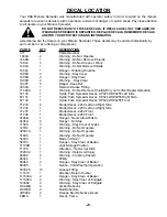
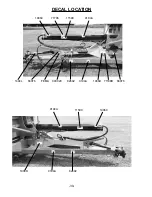
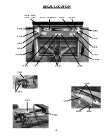
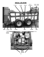
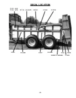
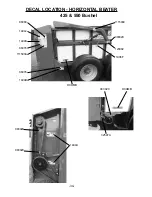
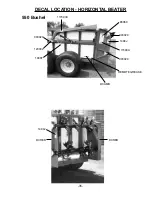
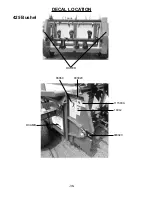
Page 38: ...36 DECAL LOCATION 425 Bushel DCRED 093020 093020 111593A 1494J 86060 DCAMB...

Page 39: ...ssing Drive Chain Push Gate Will Not Move Tractor Hydraulics Not Engaged Engage Tractor Hydraulics Low Tractor Hydraulic Flow or Have Servicing Dealer Check Tractor Pressure Flow And Pressure Hydrauli...

Page 40: ...________________________________ __________________________________________________ __________________________________________________ __________________________________________________ ______________...

Page 41: ......

Page 42: ...Manufactured by H S MANUFACTURING CO INC 2608 S HUME AVE MARSHFIELD WI 54449 715 387 3414 hsmfgco com H S MFG CO products approved for the FEMA SEAL OF QUALITY...

Reviews: