-12-
PICKUP HEAD
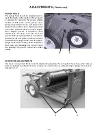
The pickup head should be adjusted accord-
ing to the height of the stubble. Pickup height
is adjusted by adjusting the gauge wheels
located at both sides of the pickup head.
Remove adjustment pin (A) and place in the
desired hole position above the gauge wheel
arm. Lower head and check for proper adjust-
ment. Repeat process if necessary. Teeth
should never be closer than 3/4’’ from the
ground. When proper adjustment is obtained,
remove pin (B) and place in hole as close as
possible below gauge wheel arm to support
gauge wheel when raising head. Excessive
tooth wear and breakage will occur if teeth
are touching the ground. Adjust both sides
equally.
A
B
ADJUSTMENTS
(Continued)
CONVEYOR ADJUSTMENTS
The cross conveyor belt tension can be adjusted by adjusting the nut against the spring on the take up
bolts (C) located on left end of cross conveyor. Correct tension is achieved when springs (D) are com-
pressed to 1.5’’.
C
D
Summary of Contents for M6
Page 4: ......
Page 15: ...15 LUBRICATION Continued B I Under Shield E G A C D F H A I Under Shield...
Page 19: ...DECAL LOCATION Continued A B L I K C Behind Shield Behind Shield A B 19 J D K I L C E G F...
Page 20: ...20 FIGURE 1...
Page 22: ...22 FIGURE 2...
Page 24: ...24 FIGURE 3...
Page 28: ...28 FIGURE 6...
Page 32: ...SERVICE NOTES 32...
Page 34: ...H S MFG CO products approved for the FEMA SEAL OF QUALITY...


