background image

7

A

B

C

Actual Floor Size

Building Size

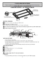
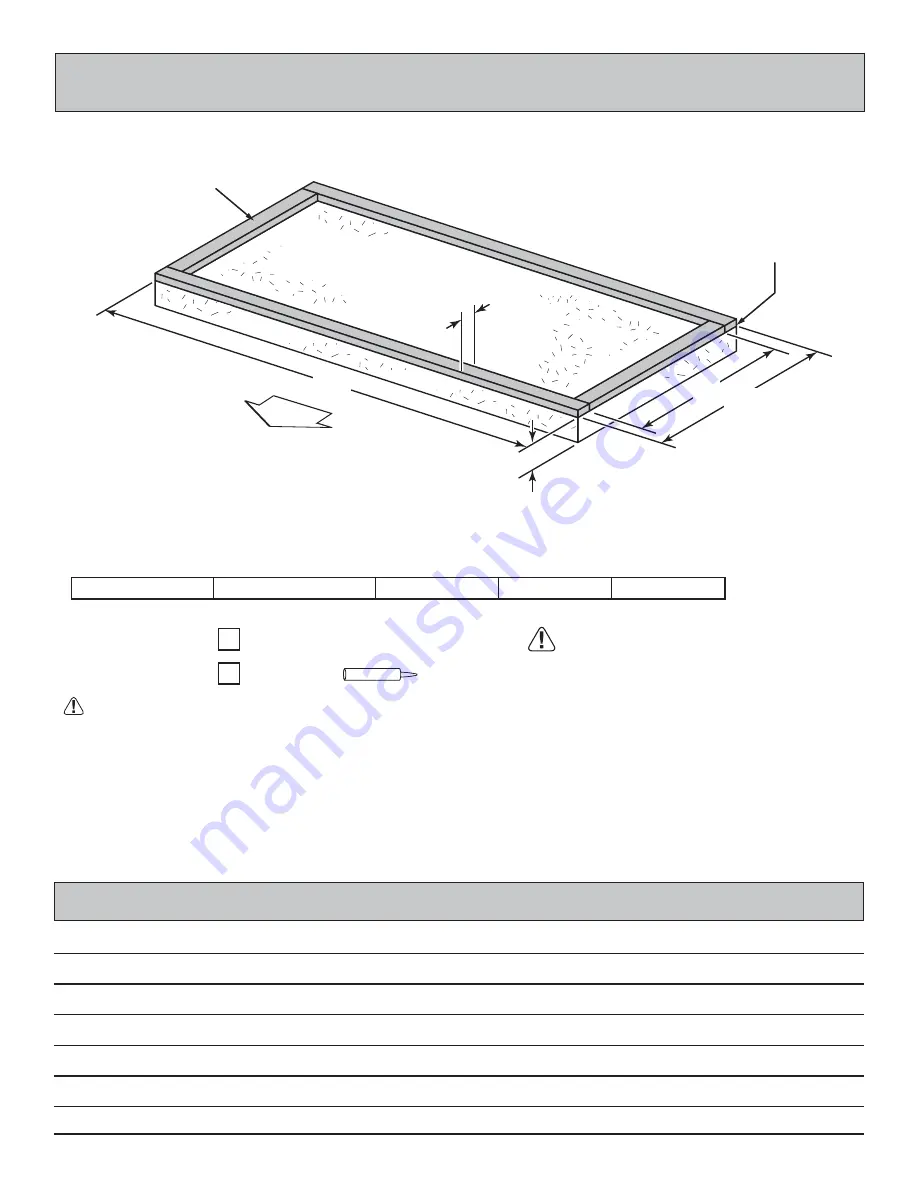
• A treated 2 x 4" (5,1 x 10,2 cm) sill plate is required when installing your shed on concrete.


Hint: Use treated lumber in your kit (you will have to cut to fit).


• Use a high quality exterior grade caulk beneath all sill plates.


• Fasten 2 x 4" (5 ,1x 10.2 cm) sill  plates to slab using approved concrete anchors 

(fasteners not included)


• Check local code for concrete foundation requirements.

68-1/4" (173,4 cm)

36" (91,4 cm)

6'x 3' (182,9 x 91,4 cm)

29" (73,7 cm)

NOTES

Treated Sill Plate

Caulk between sill plate 

and concrete.

2 x 4 x 8' (5,1 x 10,2 x 243,8 cm)

Requires:

x3

MUST be treated lumber.

Caulk

x1

      Allow new concrete slabs to cure for at least seven (7) days.

3-1/2"

(8,9 cm)

4"

(10,2 cm)

A

B

C

CONCRETE FOUNDATION

If you choose to install your kit on a concrete slab refer to the diagram below.

68-1/4"x 36" (173,4 x 91,4 cm)

DOOR

Summary of Contents for OCOEE

Page 1: ...sembly or product information call our toll free number 1 800 221 1849 or email customerservice handyhome com Our staff is ready to provide assistance April through October M F 8 00 AM to 7 00 PM EST Saturday 8 30 AM to 4 30 PM EST November through March M F 8 00 AM to 5 00 PM EST ...

Page 2: ... This page intentionally left blank ...

Page 3: ...ecific restrictions and or requirements before building ENGINEERED DRAWINGS Contact our Customer Service Team if engineered drawings are needed to pull local permits SURFACE PREPARATION To ensure proper assembly you must build your shed on a level surface Recommended methods and materials to level your shed are listed on page 6 CHECK ALL PARTS Inventory all parts listed on pages 4 5 Contact our Cu...

Page 4: ...assembly or installation Level Gloves C Clamps Framing lumber is graded for structural strength and not appearance Exterior trim is graded for one good side Always install the material leaving the best edge and best surface visible Please remember that these blemishes in no way negatively affect the strength or integrity of our product See Fig A B C A Safety Glasses Tape Measure Paint Tools Ladder...

Page 5: ...floor as this will vary depending on your specific site 3 TAB SHINGLES 1 Bundles PAINT FOR SIDING 1 Gallon Use 100 acrylic latex exterior paint 2 coats recommended CAULK 1 Tube Use acrylic latex exterior caulk that is paintable 1 GALVANIZED ROOFING NAILS 1 Lbs For shingles PAINT FOR TRIM 1 Quart Use 100 acrylic latex exterior paint REINFORCED WOOD FLOOR FRAME OPTIONAL IMPORTANT The included floor ...

Page 6: ...5 1 x 10 2 x 165 7 cm 2 x 3 x 36 5 1 x 7 6 x 91 4 cm x2 DU 2 x 3 x 45 1 2 5 1 x 7 6 x 115 6 cm x1 NE 2 x 3 x 53 5 1 x 7 6 x 134 6 cm x1 AX 2 x 3 x 68 1 4 5 1 x 7 6 x 173 4 cm x3 GPH 2 x 3 x 70 5 1 x 7 6 x 177 8 cm x2 PPO 2 x 3 x 72 5 1 x 7 6 x 182 9 cm x1 OY 2 x 3 x 76 9 16 5 1 x 7 6 x 194 5 cm x2 MLO 2 x 3 x 80 1 8 5 1 x 7 6 x 203 5 cm x2 KOR 2 x 3 x 84 5 1 x 7 6 x 213 4 cm x2 LJA Part identifica...

Page 7: ...HOOK NOTE Panel parts are not stamped x1 LEFT DOOR x1 RIGHT DOOR x1 3 8 x 5 3 16 x 48 1 x 13 2 x 121 9 cm x2 3 8 x 11 7 8 x 76 1 x 30 2 x 193 cm 3 8 x 11 7 8 x 84 1 x 30 2 x 193 cm x2 3 8 x 48 x 84 1 x 121 3 x 193 cm x1 x1 3 8 x 36 x 84 1 x 91 4 x 213 4 cm x1 3 8 x 36 x 84 1 x 91 4 x 213 4 cm x1 7 16 x 36 x 68 1 4 1 x 91 4 x 173 4 cm x1 7 16 x 40 1 2 x 48 1 x 10² 9 x 122 cm x1 7 16 x 24 x 40 1 2 1...

Page 8: ...st results and aiding in water drainage use gravel under each concrete block LEVELING METHODS If you are building your shed on a concrete foundation see the following page CONCRETE MATERIAL REQUIRED x1 4 x 4 x 8 10 2 x 10 2 x 243 8 cm Treated Lumber Fasteners for Frame to 4 x 4 3 Screws shown as one option Minimum 12 3 screws exterior grade Use only wood treated for ground contact and fasteners ap...

Page 9: ...ved concrete anchors fasteners not included Check local code for concrete foundation requirements 68 1 4 173 4 cm 36 91 4 cm 6 x 3 182 9 x 91 4 cm 29 73 7 cm NOTES Treated Sill Plate Caulk between sill plate and concrete 2 x 4 x 8 5 1 x 10 2 x 243 8 cm Requires x3 MUST be treated lumber Caulk x1 Allow new concrete slabs to cure for at least seven 7 days 3 1 2 8 9 cm 4 10 2 cm A B C CONCRETE FOUNDA...

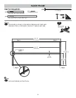
Page 10: ...asure and mark each dimension from end of boards Use two 3 nails at each mark PARTS REQUIRED Flush Flush Flush Flush Center on marks 36 121 9 cm 18 45 7 cm 1 1 2 3 8 cm 68 1 4 173 4 cm 65 1 4 165 7 cm NOTE Look for Stamp FLOOR FRAME HINT For easier nailing stand on frame BEGIN 1 x12 You have finished your floor frame FINISH 2 ...

Page 11: ...he diagonal measurement will be approximately 77 3 16 196 1 cm When the frame is level and square secure one side of frame to the 4x4 runners using one fastener at ends of each runner At the opposite end of the frame secure the frame to 4x4 runners with one fastener at ends of each runner making sure the frame remains square Fig A Once the floor frame is level and square fasten the frame at each p...

Page 12: ...sh to the floor frame Fig B Secure panel with two 1 1 2 nails in the corners 2 BEGIN 1 3 Continue attaching the panel using 1 1 2 nails 6 apart on edges and 12 apart inside panel PARTS REQUIRED Ensure your floor frame is square by installing panel and squaring frame 12 30 5 cm inside panel 6 15 cm edges of panel FLOOR PANEL Flush Flush Grid lines UP x36 x1 2 Nails Flush at corner edge Fig B 2 Nail...

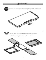
Page 13: ...evel after installing floor panel Re level if needed The floor may be used as a stable work surface for wall construction Organize your assembly procedure during the build process to avoid over handling of the walls HINT IMPORTANT ...

Page 14: ...8 1 x 13 2 x 121 9 cm x10 1 1 2 3 8 cm 12 30 5 cm 2 1 2 6 3 cm 2 1 2 6 3 cm CENTER CENTER CENTER Primed side up Flush Flush 1 1 2 3 2 cm Nails Panel will overhang AX AX GPH Center AX next to GPH on 2 1 2 flat edge as shown Secure 5 3 16 x 48 panel flush to top of GPH and centered Secure with 1 1 2 nails spaced 12 apart along panel edges ...

Page 15: ...ails spaced 6 apart along panel edges Fig B 2 3 x30 1 1 2 3 8 cm Arrange PPO flush to bottom of AX as shown Fig A Attach OO as a temporary brace as shown using 3 screws one at each side to hold the important 48 door opening IMPORTANT MEASUREMENT 48 129 1 cm 70 177 8 cm 48 121 9 cm 2 1 2 6 3 cm 2 1 2 6 3 cm Fig A Fig B Flush Flush along edge 11 7 8 x 76 6 15 2 cm 1 1 2 3 2 cm Nails Primed side up Y...

Page 16: ...T 2 Flip panel over Place temporary support NE under wall assembly Fig B Measure and place DU 1 from panel edge as shown Secure DU with 1 1 2 nails spaced 6 apart Painted Green Painted Red You have finished your side walls FINISH 4 BEGIN 1 Orient NIK MLO and LJA as shown Secure RIGHT 36 x 84 panel primed side down with 1 1 4 screws spaced 6 apart along panel edges Fig A 6 15 2 cm 1 2 5 cm 1 1 2 3 ...

Page 17: ...x 173 4 cm x1 GPH 2 x 3 x 80 1 8 5 1 x 7 6 x 203 5 cm x2 KOR Place 11 7 8 x 84 panel primed side up as shown Fig B Align panel 3 8 above GPH and flush to mark Fig B 2 2 1 2 6 3 cm 2 1 2 6 3 cm Fig A Fig B 3 7 6 cm x2 GPH GPH KOR Primed side up 11 7 8 x 84 6 15 2 cm 1 1 4 3 2 cm Flush 1 1 2 3 2 cm Nails 3 7 6 cm Screws BEGIN 1 Orient KOR and GPH on 2 1 2 flat edge Mark dimensions and secure with tw...

Page 18: ...all Align 48 x 84 panel primed side up 3 8 above GPH flush to installed panel Nail panel using 1 1 2 nails 6 apart Fig C Align 11 7 8 x 84 panel primed side up 3 8 above GPH and flush to installed panel Nail panel using 1 1 2 nails 6 apart 3 4 Fig C Fig D Primed side up Primed side up 48 x 84 6 15 2 cm 6 15 2 cm 1 1 4 3 2 cm 11 7 8 x 84 GPH GPH 1 1 2 3 2 cm Nails 1 1 2 3 2 cm Nails To draw panels ...

Page 19: ...cm Screws x2 Panel extends past floor on both sides BEGIN 1 68 1 4 173 4 cm Center back wall assembly on the 68 1 4 floor dimension Panel will extend about 1 1 2 on both sides Use 1 NE as a temporary brace Secure NE with two 3 screws Fig A 3 7 6 cm x6 Fig A Fig B NE Nail 1 1 2 nails first 1 1 2 5 1 cm Nails Fig C 3 Screws into studs x13 1 1 2 3 8 cm 2 x 3 x 45 1 2 5 1 x 7 6 x 115 6 cm x1 NE TEMPOR...

Page 20: ...ter front wall assembly on the 68 1 4 floor dimension Panel will extend about 1 1 2 on both sides 1 Use 1 OO as a temporary brace Secure OO with two 3 screws Fig A 3 7 6 cm x6 Fig A Fig B OO x1 1 1 4 x 2 1 2 x 69 3 2 x 7 6 x 175 3 cm TEMPORARY Panel extends past floor on both sides OO 3 7 6 cm Screws x2 3 Screws into studs TOESCREW x4 1 1 2 3 8 cm Fig C 3 7 6 cm Screws Nail 1 1 2 nails first 1 1 2...

Page 21: ...above floor Fig D You may install Tool Hooks higher or lower to accomodate long handle tools Secure using eight 2 screws into back wall stud Fig D Fig C 2 5 cm x8 2 5 1 cm Screws 19 x4 x3 1 1 2 3 8 cm PARTS REQUIRED F L O O R TOOL HOOKS 60 152 4 cm ...

Page 22: ...ll Assembly 1 Left 1 Right SIDE WALL INSTALLATION 3 7 6 cm x4 Secure front and back walls to side wall trim using 1 1 2 nails Fig D spaced 6 apart Secure bottom plate to floor frame using 3 nails Repeat STEPS 1 3 for LEFT side wall Remove temporary braces Fig A 1 1 2 3 2 cm Nails 1 1 2 3 2 cm Nails 3 7 6 cm Nails Flush 1 1 2 3 2 cm Nail 2 1 3 4 x50 1 1 2 3 8 cm x6 3 7 6 cm 3 7 6 cm Screw Fig D TOP...

Page 23: ... x 7 6 x 182 9 cm x1 OY Place 24 x 40 1 2 roof panel flush along edge and end of OY with grid lines up Fig A Secure using 1 1 4 screws spaced 6 apart along edge BEGIN 1 Place 48 x 40 1 2 roof panel flush with installed panel and along edge of OY with grid lines up Fig B Secure using 1 1 4 screws spaced 6 along edge 24 61 cm 48 121 9 cm 24 x 40 1 2 1 1 4 3 2 cm Screws 1 1 4 3 2 cm Screws 48 x 41 1 ...

Page 24: ...using 1 1 2 nails spaced 6 apart along edges and 12 apart inside panel Fig B 2 3 BEGIN 1 Set GPH between side wall panel notches as shown Fig A GPH should be flush with top of side walls Fig A Attach with two 3 screws through wall trim into each end of GPH Fig A Fig B Roof Panel Unit Fig A 3 7 6 cm Screws x2 GPH OY Chalk Line x42 1 1 2 3 8 cm GPH x1 2 x 3 x 68 1 4 5 1 x 7 6 x 173 4 cm GPH 3 7 6 cm...

Page 25: ... 2 5 1 cm PARTS REQUIRED OVER DOOR TRIM You have finished installing your over door trim FINISH 2 ZB BEGIN 1 Fig A 2 5 1 cm Finish Nails x6 OY Fig B OY ZB Flush ZB Center ZB over door opening and tight up to OY Attach with 2 finish nails Fig A Fig B ...

Page 26: ...8 SPACER attached to doors Attach temporary supports OO and NE with 3 screws as shown Tighten securely 4 3 7 6cm Screws 4 3 7 6cm Screws Make sure spacer is attached Tighten screws securely OFFSET Bottom edges flush 3 8 1 cm 3 8 1 cm 3 8 1 cm 3 8 1 cm OFFSET GREEN RED NE OO TEMPORARY SUPPORT OO x1 1 1 4 x 2 1 2 x 69 3 2 x 7 6 x 175 3 cm TEMPORARY SUPPORT 2 x 3 x 45 1 2 5 1 x 7 6 x 115 6 cm x1 NE ...

Page 27: ... cm Screws into the wall support and floor frame Fig C 3 8 1 cm Fig B Fig D Angle 2 5 1 cm Screw Attach temporary support OO as a ledger board 72 down from bottom of over door trim Fig A Doors will rest on OO Fig A Secure OO using two 3 screws MARK 72 from over door trim Fig A 72 182 9 cm from bottom of over door trim to top of ledger board OO MARK CENTER 3 7 6 cm x2 x10 2 5 1 cm OO 25 2 3 7 6cm S...

Page 28: ...t shown Reinforce the door trim using 3 4 screws through door panel into trim Fig A Locate screws as shown Fig B Use two screws at seams PARTS REQUIRED 19 32 x 2 1 2 x 19 1 5 x 6 3 x 48 3 cm BEA x4 x48 3 4 1 9 cm 9 22 9 cm 9 22 9 cm 3 4 1 9 cm Screws from behind Door Trim Hinge Board Fig A Door Panel Fig B 3 4 1 9 cm Screws Two Screws BEA BEA INSIDE OF DOOR 9 22 9 cm 9 22 9 cm ...

Page 29: ...WEATHERSTRIP FINISH 5 On right door center OO vertically in door opening Fig A OO will offset the right door 1 in from the door trim Fig C 3 Secure OO using six 2 screws through outside trim into OO Fig C 4 OO 2 5 1 cm Screw 1 2 5 cm OFFSET 1 2 5 cm OFFSET Secure OO using six 2 screws through outside trim into OO Fig B 2 Fig A Fig C Fig B Center OO in door opening Screws 2 5 1 cm x12 11 28 cm Appr...

Page 30: ...edge of hasp is 35 1 2 90 cm up from bottom edge of door trim Measure and mark locations and install with 3 4 screws as shown Fig B DOOR HARDWARE 2 Mount spring bolt 1 2 down from top of OO on left door using 1 screws as shown Fig A BEGIN 1 x1 3 4 1 9 cm x7 Pre drill 1 8 holes for screws OO Fig A 1 2 from top LEFT DOOR 1 8 3 2 mm Drill Bit x1 Spring Bolt 1 2 5 cm x4 4 screws in each package ...

Page 31: ... will allow you to hang additional items at the height you want Secure using 3 screws toe screwed into back wall studs as shown From outside of back wall install three 1 1 2 nails into NE 3 7 6 cm x4 3 7 6 cm Screws 1 1 2 3 8 cm Nails NE 29 PARTS REQUIRED You have finished your accessory board FINISH 3 BEGIN 1 x3 1 1 2 3 8 cm ACCESSORY BOARD ...

Page 32: ...Fig D Secure using 2 finish nails into soffit side wall frame and wall 2 x 3 trim as shown Repeat STEP 2 on opposite side You have finished installing your fascia and trim FINISH 4 1 BEGIN Fig B Fig C 30 3 8 x 2 1 2 x 40 15 16 1 x 6 3 x 104 cm x1 RIGHT 3 8 x 2 1 2 x 40 15 16 1 x 6 3 x 104 cm x1 LEFT 3 8 x 2 1 2 x 72 1 x 6 3 x 182 9 cm x1 Back wall panel Fig D TRIM PARTS REQUIRED Primed Side Out Pr...

Page 33: ...NT CAULK NOT INCLUDED DRIP EDGE NOT INCLUDED ROOF FELT NOT INCLUDED Install felt flush to all roof edges overlapping 3 Use minimal amount of roofing nails to hold in place 3 OVERLAP Flush Flush You must install drip edge to validate warranty Follow directions provided by manufacturer Install drip edge on the front side first Fig A then install felt Install drip edge on sides of roof over top of fe...

Page 34: ...to the back of roof Install first starter row upside down color up and flush to drip edge at bottom of roof panel Use 4 nails per shingle Starter row must be straight and level all the way across with lower edge of roof deck Begin where indicated on image below install first row of shingles with notch flush with drip edge 2 2 Drip Edge Notch BACK OF SHED BACK OF SHED FRONT OF SHED FRONT OF SHED ST...

Page 35: ...ke sure there is a maximum of 5 or less to the rain slot as shown below If shingles overlap at back roof edge cut to roof edge with a utility knife 1 2 5 cm 5 12 7 cm 5 12 7 cm or less Flush with rain slots Notch Notch Using your shingle hooked blade carefully cut shingles along chalk line 3 5 4 6 SHINGLES continued If more than 5 to rain slot you must install another row of shingles Flush with ra...

Page 36: ... with 1 overhang over roof edge Align remaining shingles with edge of the front drip edge Using your shingle hooked blade carefully cut shingles on a flat surface along the rain slots using a chalk line for reference You have finished shingling your roof FINISH 10 7 9 8 ...

Page 37: ...es and all edges of doors Gazebos Pergolas To validate your warranty it is necessary to properly maintain your Backyard Storage Solutions LLC unit This includes treating all of the exposed cedar and pine surfaces on your gazebo or pergola structure with an exterior grade wood preservative an exterior oil based semi transparent stain an acrylic latex exterior paint or an acrylic latex solid color e...

Reviews: