the stabilizer or elevator.
Parts Needed
• Fuselage assembly
• Servo (2) (not included)
• 24" Servo lead extension (JRPA102) (2)
• Tail cone w/mounting hardware
Tools and Adhesives Needed
• Hobby knife
• Drill
• Drill Bit: 1/16"
• Thin CA
• Masking tape
Step 1
Install the recommended servo hardware (grommets and
eyelets) supplied with your radio system onto two servos
(elevator, rudder). Use the “X” servo arm supplied
with the servo, clipping off three arms and leaving one
arm as shown below.
Step 2
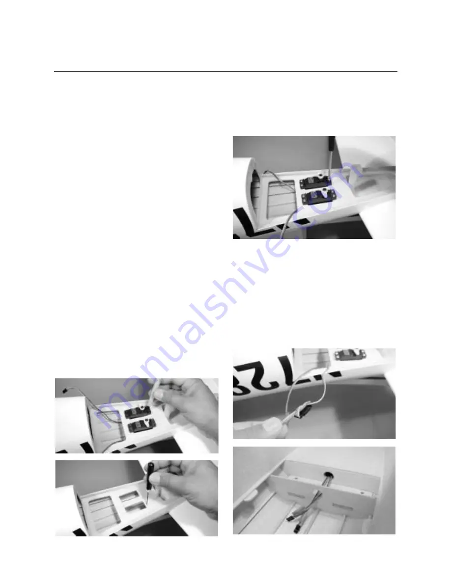
Temporarily install the rudder and elevator servos into the
openings at the rear of the fuselage and mark the location of
the servo mounting screws. Remove the servos. Use a 1/16"
drill bit to drill the holes for the servo mounting screws.
Hint
: Place a drop of thin CA onto each screw
hole to harden the wood around the hole. Allow
the CA to completely dry before installing the
servos.
Step 3
Replace the servos into the openings with the output shaft to
the rear of the fuselage as shown. Secure the servos using the
screws supplied with your radio system.
Step 4
Install a 24" servo lead extension onto the rudder and elevator
servo and secure the connectors by tying them in a knot or
use a commercial connector that prevents the servo lead and
extension from becoming disconnected. Feed the servo lead
and extensions through the installed tube in the fuselage
and into the radio compartment as shown.
Hint
: Use masking tape to identify the elevator
and rudder servo leads.
30
Section 12: Installing the Elevator and
Rudder Servos and Linkage
Continued


