15
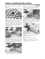
Step 5.
Repeat Steps 2–4 for the other aileron control horn.
Step 6.
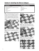
Locate the two threaded aileron wire linkages
(4-40 x 3
3
/
4
"). Thread a jam nut and clevis at least 16 turns on
to each end of each rod. Be sure these are not the longer wire
control rods to be used later for the elevator.
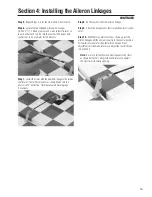
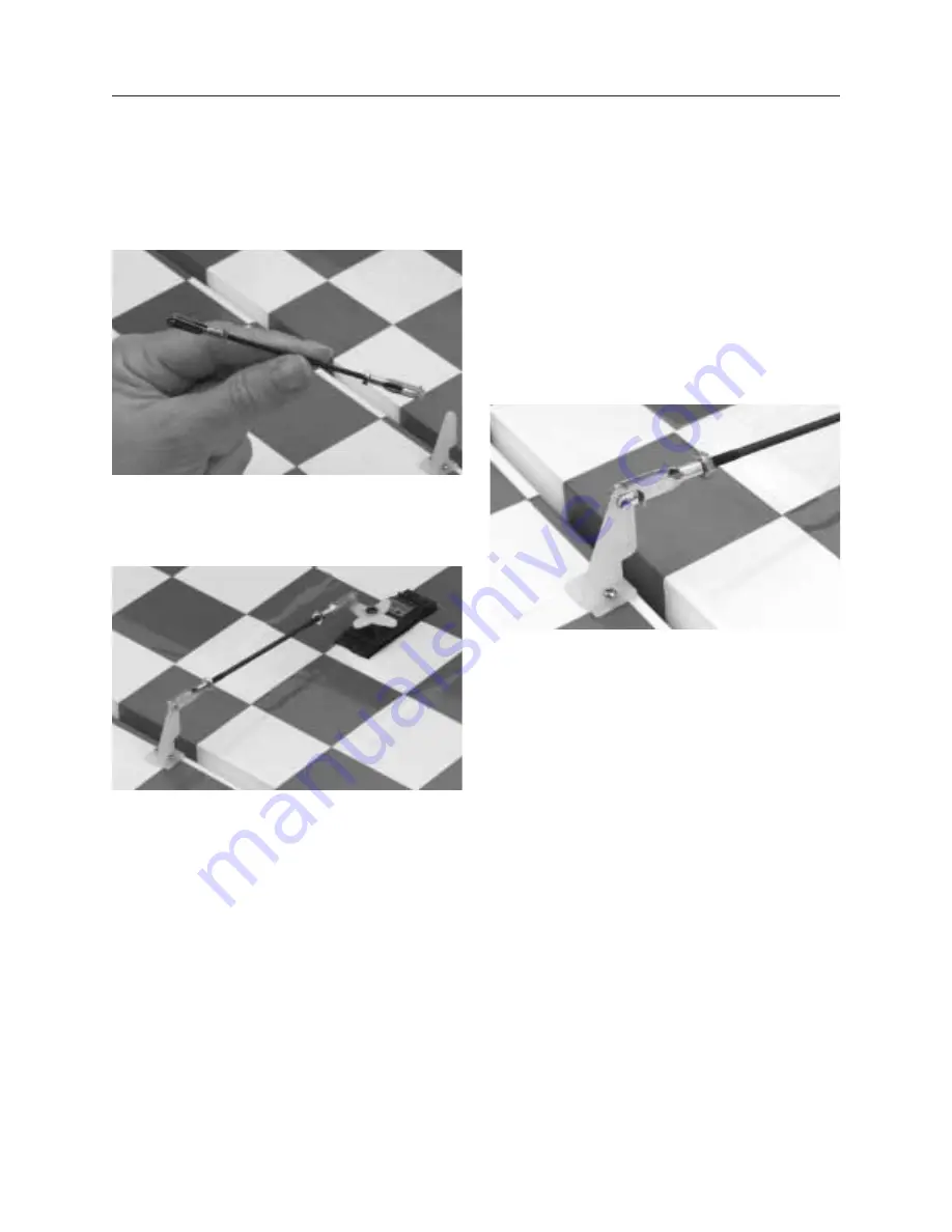
Step 7.
Install the clevis with the attached linkage to the aileron
control arm. Center the servo arm as shown. Make sure the
aileron is at 0° deflection. Hold in place with masking tape
if necessary.
Step 8.
Do the same for the other aileron linkage.
Step 9.
Attach the linkages onto their respective aileron control
horns.
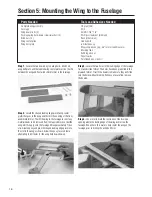
Step 10.
With the servo arm centered as shown, adjust the
aileron linkage until the aileron is exactly in the neutral position.
Follow this procedure for the other aileron linkage. Final
adjustments will be made later as you adjust the control throws
in Section 20.
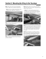
Note:
Be sure to fasten the metal clevis keeper to the clevis
as shown below. This will provide extra insurance against
the clevises accidentally opening.
Section 4: Installing the Aileron Linkages
CONTINUED
Summary of Contents for Clipped-wing Taylorcraft
Page 55: ...55 Notes ...


