background image

21

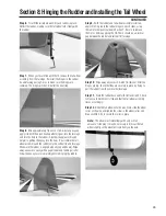
Step 6.

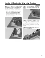
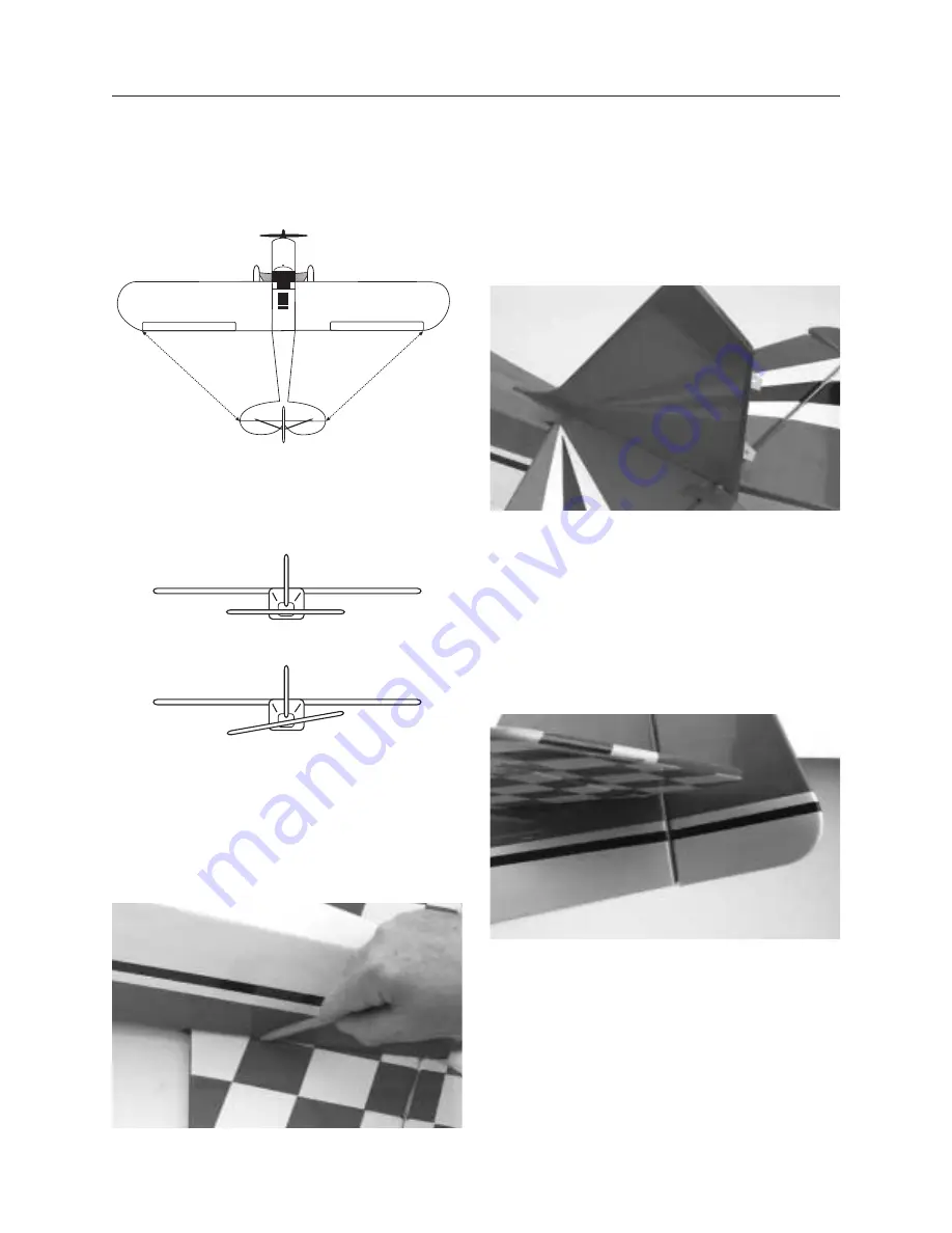
With the fuselage resting on a flat surface, align the

horizontal stabilizer by measuring from fixed points on the wing
to the outside of the trailing edge tip of the horizontal stabilizer.
Make sure the trailing edge of the horizontal stabilizer stays on
its center mark.

Step 7.

Adjust the horizontal stabilizer until you have an equal

distance on both the right and left side of the fuselage and that
the horizontal stabilizer is positioned correctly (not tilted) with
reference to the wing. Refer to the illustrations below.

Step 8.

When you're satisfied with the alignment of the

horizontal stabilizer with the wing, carefully mark the position
with a pencil at the junction where the horizontal stabilizer meets
the fuselage. The pencil should leave a slight indentation in the
covering. Mark the bottom of the horizontal stabilizer. Use
masking tape to hold it in position.

Step 9.

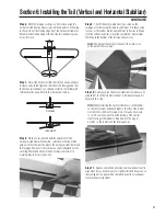
Trial fit the vertical stabilizer in position on the

fuselage, after removing the rudder and hinges. Set these aside
for now, as the rudder will be attached later in Section 8. Make
sure the vertical stabilizer is inserted completely. Some slight
trimming to the bottom of the fin may be necessary

Hint: 

The back of the vertical stabilizer slides into a slot 

at the back of the fuselage.

Step 10.

Carefully check the vertical stabilizer to make sure it's

aligned 90° to the horizontal stabilizer. A 90-degree triangle is
helpful in this step.

Hint:

When installing the vertical stabilizer, use the rudder

to check for proper stabilizer height so the rim of the rudder
matches trim scheme at fuselage rear. It may be necessary
to cut off a small amount from the bottom of the vertical
stabilizer to get the rudder to drop down to the proper
position so the rudder and the fuselage align.

Step 11.

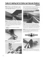
Double-check the horizontal stabilizer and vertical fin

alignment. It may be necessary to slightly trim the balsa wood on
the fuselage or tail parts with a sharp hobby knife or sandpaper
to achieve exact alignment.

Section 6: Installing the Tail (Vertical and Horizontal Stabilizer)

CONTINUED

Correct

Incorrect

Summary of Contents for Clipped-wing Taylorcraft

Page 1: ...n 1702 mm Wing Area 1315 sq in 84 4 dm sq Flight Weight 13 15 lb 5 9 6 8 kg Recommended Engines 1 08 1 48 2 Stroke 1 20 1 82 4 Stroke Zenoah 23 Gas 90 prebuilt Giant scale legal Precovered with genuine UltraCote Featuring one of a kind scale trim scheme Prefinished fiberglass cowl Gas or glow option ...

Page 2: ...talling the Control Horns 26 Section 10 Installing the Main Landing Gear and Wheel Pants 29 Section 11 Installing the Engine Glow Option 32 Section 12 Installing the Engine Gas Option 34 Section 13 Assembling and Installing the Fuel Tank Glow Gas 35 Section 14 Installing the Radio 37 Section 15 Installing the Control Linkages 39 Section 16 Attaching the Cowling 44 Section 17 Attaching the Windshie...

Page 3: ...odel just like yours This is a stand off scale model however the experienced modeler will find that this kit has the basic components that will allow for numerous variations If you decide to make scale variations we would be very interested in learning about your effort Any changes in the basic parameters of the kit could result in a model that does not perform as this kit has been designed to do ...

Page 4: ...uter radio is used Recommended JR Systems JR XF652 JR XP783 JR XP8103 PCM10X Engines 1 08 1 48 2 Cycle Engines 1 20 1 82 4 Cycle Engines Zenoah G23 Gas Engine Recommended Recommended Recommended 2 Cycle Engines 4 Cycle Engines Gas Engine Webra 1 20 Saito 1 20 1 80 Zenoah G23 Gasoline Engine MDS 1 48 Saito 1 20GK 1 80GK Saito 1 82 Twin MDS 1 48 Saito 1 80 Zenoah G 23 JR 8103 10X ...

Page 5: ...e glue 6 minute epoxy 30 minute epoxy Blue Locktite Z 42 Canopy glue R C 56 Silver solder Stay Brite Masking tape Tools Drill Drill Bits 1 16 1 8 5 32 1 4 Soldering iron Phillips screwdriver small and medium Z bend pliers Pliers Hex Wrench 1 16 Round file small Moto tool with sanding drum Hobby knife with 11 blade Mixing stick Epoxy brush 90 degree triangle Sanding sticks medium Medium sandpaper S...

Page 6: ... White UltraCote HANU870 Black UltraCote HANU874 Red White 2 Checkered HANU944 Pushrod and accessories Plywood die cut motor spacer parts Hardware bags for control linkages Fuel tank and hardware Wheels Metal Motor Mounts w Hardware HAN2033 Tail Wheel and Hardware HAN2087 Windshield Set HAN1854 Wing Strut Set HAN1858 Wing mounting hardware Other Parts Note Photos of products may vary slightly from...

Page 7: ...he T pin is snug against the wing Step 3 Slide the aileron onto the wing until there is only a slight gap The hinge is now centered on the wing panel and aileron Remove the T pin and snug the aileron against the wing panel This will ensure that the hinges are centered Step 4 Deflect the aileron and completely saturate the hinge with thin CA glue The aileron s front surface should lightly contact t...

Page 8: ...n in place Step 8 After both ailerons are securely hinged firmly grasp the wing and aileron and check that the hinges are securely glued and cannot be pulled out Do this by applying medium pressure trying to separate the aileron from the wing Use caution not to crush the wing structure Note Work the aileron up and down several times to work in the hinges and check for proper movement Section 1 Hin...

Page 9: ... of the wing is accurate Step 3 The wing has 0 dihedral Place the wing on a large flat surface with both wing panels resting on the flat surface If necessary sand the wing joiner until this is achieved There should be no gap in the wing center Step 4 Separate the wing halves and remove the wing joiner Once you re satisfied with the trial fit of the wing panels you can prepare to epoxy the wing pan...

Page 10: ... epoxy coated half of the wing brace into the wing joiner cavity of the wing panel up to the centerline Use rubbing alcohol and a paper towel to clean up any excess epoxy Step 8 Apply a generous amount of epoxy into the wing brace cavity of the other wing panel Note You will need to mix additional epoxy to complete the wing joining process Step 9 Next apply epoxy to all sides of the exposed area o...

Page 11: ...rely Place the wing top side up on a flat surface Apply more masking tape to the wing center joint Make sure the wing halves are still properly aligned Allow the wing joint epoxy to cure completely overnight Note It is helpful to use wax paper underneath the wing center while the epoxy is curing so any excess epoxy will not adhere to the work area surface Step 12 After the wing center joint is cur...

Page 12: ... servos grommets and eyelets Install a servo extension lead to the servo as well Secure the connectors with by tying them in a knot and use electrical tape to secure in place and prevent opening in flight Hint It is always a good idea to secure the servo connectors and servo extension together to prevent the wires from becoming unplugged inside the wing Step 3 Trial fit the servo into the servo op...

Page 13: ...hrough the wing servo opening Attach a weight small nut to a length of string and drop it through the servo lead opening in the wing and allow it to exit through the servo opening in the bottom of the wing Step 8 Once you have the string threaded through the wing tie it to the servo lead extension connector Carefully thread the servo wire extension through the wing Step 9 To prevent the extension ...

Page 14: ...the servo control arm as shown Note the portion of the servo arm we use is the one pointing toward the wingtip Remember to locate the control horn so the clevis holes are directly above the hinge line of the aileron Step 2 Place the center of the control horn on the aileron at the mark made in the previous step Mark the hole positions of the control horn Step 2 photo Step 3 Remove the control horn...

Page 15: ...ion Hold in place with masking tape if necessary Step 8 Do the same for the other aileron linkage Step 9 Attach the linkages onto their respective aileron control horns Step 10 With the servo arm centered as shown adjust the aileron linkage until the aileron is exactly in the neutral position Follow this procedure for the other aileron linkage Final adjustments will be made later as you adjust the...

Page 16: ...he wing and fits into the opening of the front windshield former Trial fit the wing to the fuselage to see if any material needs to be removed from the tapered block so that the wing will fit snugly onto the fuselage Mix approximately 1 4 oz of 6 minute epoxy and glue the shaped leading edge piece into the slot in the wing as shown Allow the epoxy to cure before attempting to drill holes for the w...

Page 17: ... not drill through the leading edge material completely as you will drill into the square open wing skylight area of the wing We suggest using a piece of masking tape on the drill bit to mark the depth you plan to drill Step 9 Remove the wing from the fuselage Mix approximately 1 4 ounce of 6 minute epoxy and glue the dowels into the holes in the leading edge of the wing you just drilled Wipe away...

Page 18: ...sition on the fuselage by first sliding the leading edge dowels into the fuselage front wing dowel support bulkhead that makes up the frame for the front windshield Step 14 Check the wing alignment at the rear with reference to the centerline mark Also check the wing alignment by measuring from each wing tip to the center of the fuselage tail where the horizontal and vertical stabilizers are mount...

Page 19: ...he wing bolt hold down block to keep from crushing the wood Step 17 A small drop of CA glue will help hold the blind nuts in place Use care not to get the CA on the inner threads of the blind nuts Step 18 Fit the wing into position on the fuselage Thread the wing hold down screws into the wing and loosely tighten them Check the alignment of the wing by measuring the alignment as you did in Step 14...

Page 20: ...se a straight edge to locate and mark the centerline of the horizontal stabilizer This will serve as a reference point when installing the horizontal stabilizer onto the fuselage Step 3 By noting the centerline you marked you can position the horizontal stabilizer so that it s centered on the fuselage opening where the vertical stabilizer will go and the rear of the fuselage Step 4 Mark the center...

Page 21: ...n the fuselage after removing the rudder and hinges Set these aside for now as the rudder will be attached later in Section 8 Make sure the vertical stabilizer is inserted completely Some slight trimming to the bottom of the fin may be necessary Hint The back of the vertical stabilizer slides into a slot at the back of the fuselage Step 10 Carefully check the vertical stabilizer to make sure it s ...

Page 22: ...rks made previously and measuring the wing to horizontal stabilizer as done in Step 5 and Step 6 Clean excess epoxy away from the horizontal stabilizer fuselage junction with rubbing alcohol and a paper towel Use masking tape to hold the horizontal stabilizer in place while epoxying the vertical stabilizer in place in the next step Step 16 Mix 1 2 ounce of 30 minute epoxy and apply in the fuselage...

Page 23: ...tor half proper aligned left and right apply thin CA glue to the hinges on both sides Wipe away any excess CA with CA debonder and a paper towel Step 3 After the hinges are dry check that they are securely in place by trying to pull the elevator from the horizontal stabilizer Use care not to crush the structure Step 4 Repeat Steps 1 3 for the other elevator half Step 5 Flex the elevator halves up ...

Page 24: ...here it s flush with the fuselage bottom Note where the wire rests in reference to the rudder Using a felt tipped pen mark the position where the hole is to be drilled into the rudder Also mark the position of the slot where the nylon bearing will fit into the back of the fuselage This slot should be positioned so it is centered on the fuselage tail section Step 3 photo Step 4 Remove the rudder fr...

Page 25: ...pletely before hinging the rudder Step 9 With the rudder and tail wheel assembly installed apply thin CA glue to the rudder hinges on both sides using the same techniques learned in Section 1 Be sure to remove the T pins before applying the CA There should be a minimal gap between the rudder and vertical fin fuselage Step 10 Wipe away any excess CA with CA remover After the hinges are dry check th...

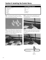
Page 26: ...alling the control horn on the right elevator first as relates to pilot sitting in cockpit Measure 1 2 in from the inboard end of the elevator as shown below Make a mark with a felt tipped pen Step 3 Locate one control horn and trial fit the horn on the elevator with the edge closest to the fuselage adjacent to the mark you made in Step 2 Step 4 Position the horn so the holes for the clevis are di...

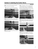
Page 27: ...the rudder Measure up 1 3 8 from the bottom of the rudder on one side as shown below You will find the control horn will be centered on the black trim line of the rudder This will serve as the reference point and represent where the bottom edge of the control horn will be located Step 9 Place one control horn adjacent to the mark you made in Step 8 Position it so the clevis holes are lined up over...

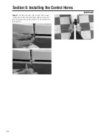
Page 28: ...s with a 1 16 drill bit Install a rudder control horn on both sides of the rudder with two screws and two nuts Again make sure the control horns are centered over the hinge line Section 9 Installing the Control Horns CONTINUED ...

Page 29: ...5 8 back from the firewall as shown above With the main gear in position mark the bolt hole locations on the fuselage using a sharp pencil or felt tipped pen Step 3 Use a 1 8 drill bit and drill the main landing gear bolt holes in the fuselage bottom Step 4 Locate the landing gear mounting bolts washers and nuts Mount the main landing gear to the fuselage Step 5 The main wheels will be installed a...

Page 30: ...pants as a brace or reinforcement for mounting the wheel pant to the landing gear Use a pencil to mark the position of the plywood squares inside the wheel pants Step 10 Mix up approximately 1 ounce of 30 minute epoxy Epoxy both plywood pieces to the inside of each wheel pant We recommend using a square piece of fiberglass cloth to cover the wood squares coating with 30 minute epoxy The use of the...

Page 31: ...lt down Step 18 Mount the wheel pant to the axle and screw in the 4 40 bolt into the small hole above the axle so that it screws into the blind nut Be sure to include the black clip between the bolt and main gear as this will be used later to connect the music wire shock system to the main landing gear Before tightening the 4 40 bolt slide on a wheel collar the wheel and another wheel collar onto ...

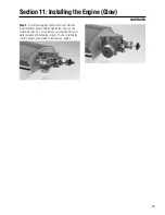
Page 32: ... screws and nuts 4 5 mm screws and nuts and washers Note the larger screws will be used to mount the metal motor mount to the firewall Step 3 Before you mount the engine mounts note there are slots in the firewall so the width of the space between the mounts can be adjusted This will allow mounting of engines with different size crankcases A square 3 4 plywood spacer will be used to mount some eng...

Page 33: ...h has been confirmed tighten the screws on the metal motor mounts You can remove your engine at this point while completing the following sections Prior to installing the control linkages you will want to remount your engine Section 11 Installing the Engine Glow CONTINUED ...

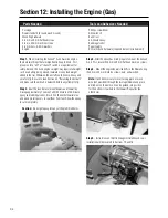
Page 34: ...alancing the Aircraft and make sure the aircraft is balanced before any attempt to fly Step 2 Seal the round motor mount dowels and firewall by mixing approximately 1 ounce of a 50 50 mixture of 30 minute epoxy and rubbing alcohol Brush it on the entire firewall area and wood motor spacers to seal them from fuel Allow the epoxy to cure completely Caution Do not get epoxy into any of the predrilled...

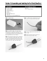
Page 35: ... in the stopper so an equal amount of tube extends from each side This tube will be the fuel tank pickup tube that provides fuel to the engine Step 3 Slide the smaller of the two plastic caps over the brass tube on one side of the black rubber stopper so the small peg faces away from the stopper toward the inside of the fuel tank The longer cap is placed on the other side of the rubber stopper so ...

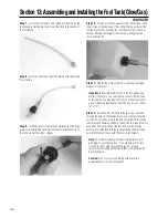
Page 36: ...ch is the vent so you can properly connect the fuel tank to the engine You may want to mark one of the tubes with a piece of masking tape identifying which one it is i e either V or F Step 12 Install the fuel tubing onto the two tubes and feed through the holes in the firewall as you press the fuel tank into position Foam can be used in the tank compartment to provide some vibration damping and he...

Page 37: ...ou re satisfied with the servo placement mark the mounting holes for the rudder and throttle servos Remove all of the servos from the tray except the elevator servo Step 3 Locate the two pieces of 1 square x 1 16 thick plywood Cut in half and epoxy together to make two 1 8 thick pieces These will be used to raise the elevator servo up high enough to clear the rudder servo in the middle of the serv...

Page 38: ... fuselage back to the vertical fin Install the switch on the left side of the rear fuselage so that it is easily accessible Step 8 Mount the switch harness Connect the three servos in the fuselage to the receiver and then connect the switch harness to the receiver and battery pack as outlined in your radio s instructions Turn on your transmitter and receiver and center your transmitter trims Then ...

Page 39: ...ponents for the elevator control linkage made up of a wooden pushrod three threaded rods 12 6 three clevis two pieces of nylon thread three clevis keepers and three jam nuts Since the Clipped Wing Taylorcraft uses a split elevator you will construct a Y pushrod that has two threaded rods on one end of the wooden pushrod for the two elevators and one shorter threaded rod to connect to the servo arm...

Page 40: ... 12 threaded rods into the holes on either side of the wood pushrod Step 9 Once you re satisfied with the fit mix a small amount of 6 minute epoxy and apply it to the holes and areas the rods will fit into Coat the joint with epoxy wrap with half of the nylon thread provided and allow it to cure Step 10 Carefully cut away the covering at the tail of the fuselage where the pushrods exit Note there ...

Page 41: ...fit Coat with epoxy wrap with nylon and allow to cure completely Step 17 Before attempting to reinstall the completed elevator pushrod make sure the epoxy has cured completely Step 18 Reinstall the elevator pushrod and clevises and attach to the elevator control horns and elevator servo arm Make any necessary mechanical adjustments so the elevators are at nuetral when the servo arm is electrically...

Page 42: ...ect the throttle arm to the throttle servo Trial fit the rod and note where it will pass through the fuselage formers The location of the opening in the firewall for the pushrod will depend on the type of engine installed We show the installation of a MDS 1 48 2 stroke engine to illustrate the steps in the installation and adjustment of the throttle linkage Once you have determined the linkage pat...

Page 43: ...ow Step 28 Double check the alignment of the elevator rudder and throttle linkages Don t forget the ailerons Adjustments can be made at two points for each linkage at the servo arm and at the control horn Sometimes it only takes one adjustment other times it requires both adjustments Once you have made all of your mechanical adjustments you can then proceed to make any electrical adjustments throu...

Page 44: ... mounted in the Taylorcraft Step 3 Carefully cut out using a moto tool Note If you re using another type of engine it will be necessary to carefully cut portions of the cowl that are located differently from where it is shown with the installation of the MDS 1 48 Step 4 Slide the cowling onto the fuselage Note It may be necessary to trial fit the cowl with and without the muffler attached to the e...

Page 45: ...he cowl is pulled down tightly and held securely prior to drilling a hole As each hole is drilled check to make sure the cowl has not moved Insert the rubber grommets into the holes to help reduce vibration and subsequent cracking of the cowling Use blind nuts to mount the cowl to the fuselage Step 8 Epoxy the cooling shroud scoop to the top of the cowl Section 16 Attaching the Cowling CONTINUED ...

Page 46: ...g sure not to remove too much material Trial fit the overhead window to see if any trimming is needed Periodically check the fit of the windshield and side windows to the fuselage while trimming Step 3 Trial fit the windshield and side windows to the fuselage Step 4 After confirming the fit of the windshield and side windows attach the side windows to the fuselage from the inside using canopy glue...

Page 47: ... using a pencil or felt tipped pen Also mark the location the four screws will be positioned to hold the overhead window in place Step 8 Use a 1 16 drill bit to drill holes in the clear overhead window Place the overhead window in position on the wing center at the location previously marked in Step 7 and mark the location of the screws onto the wing center section using a pencil or felt tipped pe...

Page 48: ...t and tail brace material and their associated hardware Step 2 Locate the mounting points for the wing struts in each wing panel The holes are small and the covering will have to be cut away to expose the blind nuts mounted in the wing to accept the wing struts mounting screws Step 3 Locate the mounting points for the struts on either side of the main landing gear Step 4 Attach the wing to the fus...

Page 49: ...brace is aligned properly as shown below Step 8 Use a drill and 1 16 drill bit to drill holes in the stabilizer and rudder at the locations you marked Step 9 Mount the tail brace to the fin first using the hardware provided On the stabilizer pass the screws through the holes in each side and trial fit the bottom tail braces to the stabilizer fuselage sides Mount the bottom tail braces to the stabi...

Page 50: ...trim and trial fit to the fuselage former above the fuel tank where the front windshield is mounted Finishing the cockpit and Installing Pilot s Seat Step 4 Before installing the scale seat you will need to mount the seat rails to the floor of the cockpit Once mounted paint the interior of the fuselage cockpit a matching white color We used Tamiya s acrylic white paint The throttle linkage coverin...

Page 51: ...ant part of preparing the aircraft for flight is properly balancing the model This is especially important when various engines are mounted Caution Do not inadvertently neglect this step The recommended C G center of gravity location for the first flights with the Clipped Wing Taylorcraft is 4 1 4 inches from the leading edge of the wing If necessary move the batter pack or add weight either to th...

Page 52: ...hat all controls aileron elevator throttle rudder move in the correct direction Step 3 Before you fly be sure that your batteries are fully charged per the instructions included with your radio Adjusting Your Radio Step 1 Completely read the instructions included with your engine and follow the recommended break in procedure Step 2 At the field adjust the engine to a slightly rich setting at full ...

Page 53: ...heir internal combustion engine s nor will I operate models with extremely hazardous fuels such as those containing tetranitromethane or hydrazine 9 I will not operate models with pyrotechnics any device that explodes burns or propels a projectile of any kind including but not limited to rockets explosive bombs dropped from models smoke bombs all explosive gases such as hydrogen filled balloons or...

Page 54: ... 2 All officials must be off the course except for the starter and his her assistant 3 On the course is defined as any area beyond the pilot staging area where actual flying takes place B I will not fly my model aircraft in any organized racing event which does not comply with paragraph A above or which allows models over 20 pounds unless that competition event is AMA sanctioned Note Refer to AMA ...

Page 55: ...55 Notes ...

Page 56: ... 2001 Horizon Hobby Inc 4105 Fieldstone Road Champaign IL 61822 www horizonhobby com HAN1850 46 ...

Reviews: