32
Section 11: Installing the Engine (Glow)
Fuselage
Metal engine mounts (2)
Mounting hardware
Engine
Phillips screwdriver
Allen wrench
30-minute epoxy
Epoxy brush
Rubbing alcohol
Paper towels
Parts Needed
Tools and Adhesives Needed
Note:
When any engine is properly mounted the distance
from the engine firewall to the back of the engine drive
washer should be 6".
Step 1.
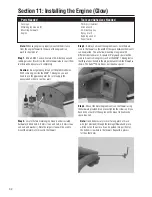
Mix a 50/50 1-ounce mixture of 30-minute epoxy and
rubbing alcohol. Brush it on the entire firewall area to seal it from
fuel. Allow the epoxy to cure completely.
Caution:
Do not get epoxy into any of the predrilled holes.
With some engines like the MDS
™
1.48 engine, you will
need to use the plywood spacer. Be sure to apply the
epoxy/alcohol mix to seal it as well.
Step 2.
Locate the two metal engine mounts and associated
hardware (4 blind nuts, 4.5 mm screws and nuts, 4.5 mm screws
and nuts, and washers). Note the larger screws will be used to
mount the metal motor mount to the firewall.
Step 3.
Before you mount the engine mounts, note there are
slots in the firewall, so the width of the space between the mounts
can be adjusted. This will allow mounting of engines with
different size crankcases. A square 3/4" plywood spacer will be
used to mount some engines (such as the MDS
™
1.48 engine) so
that they are positioned at the proper distance from the firewall as
shown. The Saito™ FA-180 does not require a spacer.
Step 4.
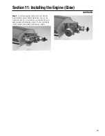
Mount the metal engine mounts on the firewall using
the hardware provided. Do not over-tighten the screws until you
have done a trial fit of the engine on the mount to finalize the
space required.
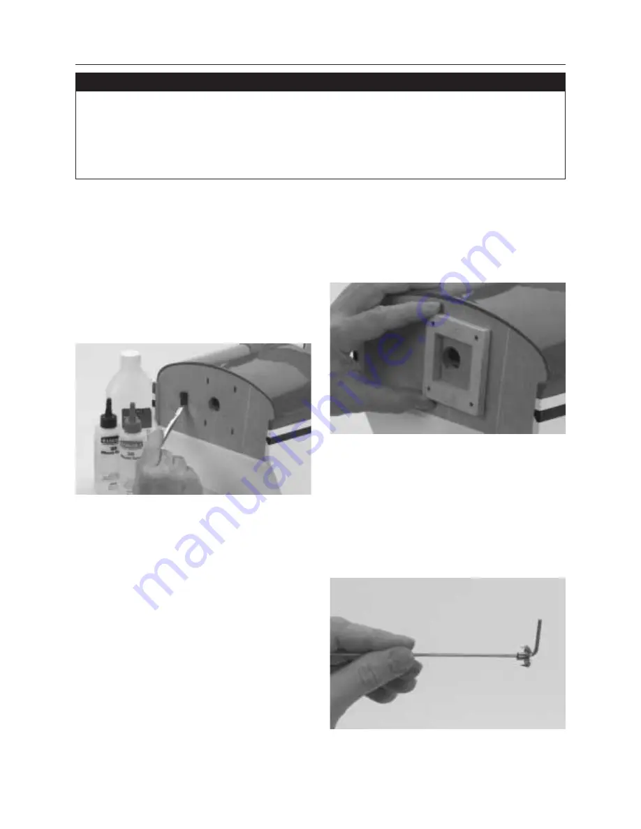
Note:
It will be necessary to insert a long piece of music
wire (not provided) through the fuselage/firewall and place
a blind nut on the wire so it can be guided into position for
the bottom screw hole in the firewall. Repeat this process
for the other holes.
Summary of Contents for Clipped-wing Taylorcraft
Page 55: ...55 Notes ...

