43
Section 15: Installing the Control Linkages
CONTINUED
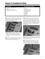
Step 26.
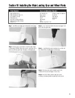
The Z-bend is attached to the servo arm in the second
hole from the end of the arm. Minor adjustments to the carburetor
opening can be made by screwing the clevis in or out. Begin your
adjustments with the throttle set at the half open position when the
arm of the servo and the rod are 90° to each other and the servo is
electrically centered.
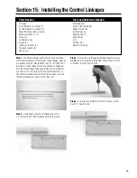
Step 27
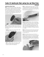
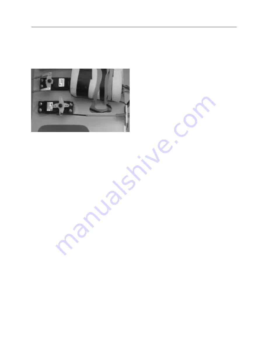
. Make a pushrod brace from scrap wood to attach the
pushrod outer sleeve to the servo tray, as shown below.
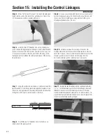
Step 28.
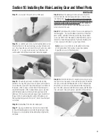
Double-check the alignment of the elevator, rudder
and throttle linkages. Don't forget the ailerons. Adjustments can
be made at two points for each linkage, at the servo arm and at
the control horn. Sometimes it only takes one adjustment, other
times it requires both adjustments. Once you have made all of
your mechanical adjustments, you can then proceed to make any
electrical adjustments through you transmitter, if applicable.
Check each clevis to make sure there is a metal clip over each
clevis to prevent accidental opening. Tighten all jam nuts on the
aileron linkages. Also, check to make sure the linkage movement
is free for each control. There should be no binding of any of the
control surfaces or linkages.
Summary of Contents for Clipped-wing Taylorcraft
Page 55: ...55 Notes ...

