24
EN
5/8 inch
(16mm)
5/8 inch
(16mm)
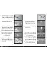
129.
Install the receiver in the fuselage. Mount any remote
receivers in the fuselage using hook and loop tape. Follow
the instructions included with the receiver for the correct
locations for the remote receivers.
Apply a small amount of 5-minute epoxy to the
hook and loop tape to secure it to the radio tray.
130.
Remove the covering from the fuselage side using a hobby
knife and #11 blade. Mount the switch using the hardware
provided with the switch.
The radio and ignition switch can also be installed in the
cockpit floor. Some event regulations may require the switches
be located so they can be accessed in an emergency.
131.
Open the side door by rotating the lever counterclockwise.
132.
Use a 2.5mm hex wrench to remove the screws securing the
cockpit fl oor.
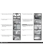
RUDDER PULL-PULL CABLE INSTALLATION
134.
Thread a ball end eight turns on each of the four cable
fi ttings.
135.
Use the radio system to center the rudder servo. Place
the rudder servo arm on the servo so two of the arms are
perpendicular to the servo centerline. Remove the two arms
that are parallel to the servo centerline using side cutters.
136.
Enlarge the holes that are 5/8 inch (16mm) from the center
of the servo using a pin vise and 1/8-inch (3mm) drill bit. The
rod ends will attach to these holes.
137.
Attach two of the rod ends to the rudder servo arm using
two M3 x 10 socket head cap screws, two M3 locknuts and
two M3 washers. Tighten the hardware using a 2.5mm hex
wrench and 5.5mm nut driver.
138.
Insert the ends of the cables into the tubes in the fuselage.
Use low-tack tape to keep the cables from entering the tubes.
133.
Remove the fl oor and set it aside.Route the leads for the
ailerons and fl aps through the cockpit fl oor. Secure the leads
using tie-wraps, tape, or any other preferred method to
prevent them from interfering with the operation of the model.


