26
EN
148.
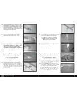
Slide the elevator pushrod into the pushrod tube. Use the
radio system to center the elevator servo. Install the servo
arm so it is 90 degrees to the pushrod.
151.
Thread the ball end on the elevator pushrod. Adjust the ball
end so the elevator is centered when the elevator servo is
centered. Once adjusted, secure the ball end to the control
horn using an M3 x 15 socket head cap screws, two M3
washers and an M3 locknut. Tighten the hardware using a
2.5mm hex wrench and pliers.
150.
Prepare and attach the second elevator pushrod. Attach the
servo arm to the elevator servo.
TAIL WHEEL INSTALLATION
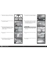
152.
Use the hardware included with the tail wheel to secure the
wheel in the fork. The brass spacers are located on either
side of the wheel when placed in the fork.
153.
Secure the wheel using the M4 locknut. Use a 3mm hex
wrench and 7mm nut driver to tighten the hardware. Make
sure not to over-tighten the hardware, preventing the wheel
from rotating.
154.
Place the tiller arm on the bottom of the rudder with the
leading edge of the arm aligned with the rudder hinge line.
Make the locations for the mounting screws on the rudder
using a felt-tipped pen.
156.
Prepare the holes by threading an M3 x 12 sheet metal screw
in each hole. Remove the screw and place a few drops of thin
CA in each hole. Once the CA has fully cured, use the screws
and a #2 Phillips screwdriver to attach the tiller arm on the
bottom of the rudder.
155.
Use a drill and 5/64-inch (2mm) drill bit to drill the two
locations for the tiller arm mounting screws.
157.
Remove the nuts from the screws on the tail wheel leaf
spring. Slide the stabilizer brace mount on the forward screw.
149.
Thread the ball end on the elevator pushrod. Adjust the ball
end so the elevator is centered when the elevator servo is
centered. Once adjusted, secure the ball end to the control
horn using an M3 x 15 socket head cap screws, two M3
washers and an M3 locknut. Tighten the hardware using a
2.5mm hex wrench and pliers.


