16
EN
10.
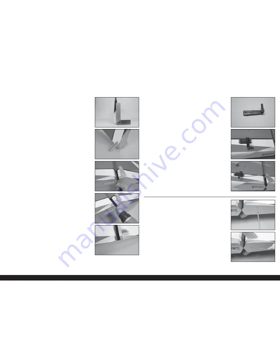
Assemble the rudder linkage using a 4
1
/
2
-inch (114mm)
linkage and ball end. Attach the ball end to the control
horn using a 4-40 x 5/8-inch socket head cap screw and
4-40 locknut. Tighten the hardware using a 3/32-inch
hex wrench and 1/4-inch nut driver. Adjust the linkage so
the rudder is centered while the rudder servo is centered
using the radio system.
1.
Thread a #4 x 5/8-inch self-tapping socket head cap
screw into the two pre-drilled holes in the bottom of the
rudder using a 3/32-inch hex wrench. Remove the screws
before proceeding.
2.
Place 2 to 3 drops of thin CA in each hole to harden
the surrounding wood. Allow the CA to fully cure before
proceeding.
1.
2.
TAIL WHEEL INSTALLATION
5.
Attach the rudder to the fi n using the hinge wire. Start the
wire in the bottom hinge by hand.
6.
Attach a drill to the wire, then use the drill to install the
wire through the remaining hinges.
7.
Complete the hinge wire installation by inserting the wire
so only 1/8-inch (3mm) of the wire protrudes beyond the
bottom of the rudder.
3.
Prepare and install the rudder control horn, starting with
the upper horn. Check that the rudder rests perpendicular
to your work surface when the rudder is resting on the
control horn and hinge line as shown using a square.
8.
Attach the ball link to the rudder servo arm.
4.
Repeat the process to install the lower control horn. Allow
the epoxy to fully cure before proceeding.
9.
Center the rudder servo using the radio system. Attach
the servo arm to the rudder servo perpendicular to the
servo center line.
8.
9.
10.
3.
4.
5.
6.
7.


