25
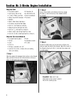
Required Parts
• 27
1
/
8
-inch (690mm) pushrod, rudder
• 26
3
/
4
-inch (680mm) pushrod, elevator
• Pushrod snap keeper (2)
Required Tools and Adhesives
• Felt-tipped pen
• Pliers
• Side cutters
• Pin drill
• Drill bit: 5/64-inch (2mm)
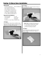
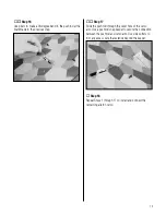
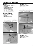
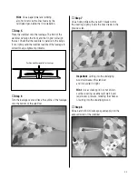
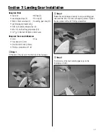
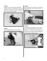
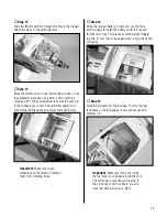
Step 1
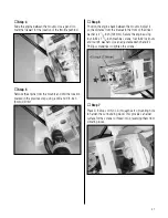
Enlarge the hole 1/2-inch (13mm) from the center of the
servo horn using a 5/64-inch (2mm) drill bit. Use side
cutters to remove any unused arms from the horn.
o
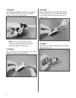
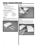
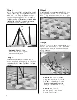
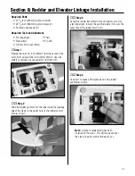
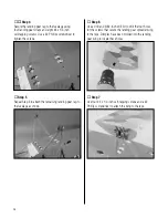
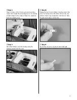
Step 2
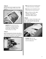
Slide the rudder pushrod into the tube inside the fuselage.
Attach the clevis to the center hole of the rudder control
horn as shown.
o
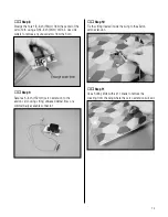
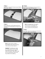
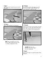
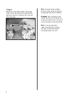
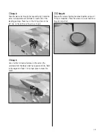
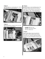
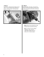
Step 3
Center the rudder transmitter trim and rudder servo. Use
a felt-tipped pen to mark the pushrod where it crosses the
outer hole of the rudder servo horn.
o
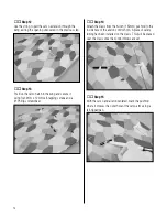
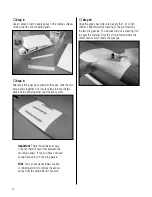
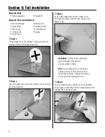
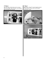
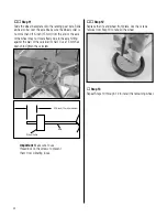
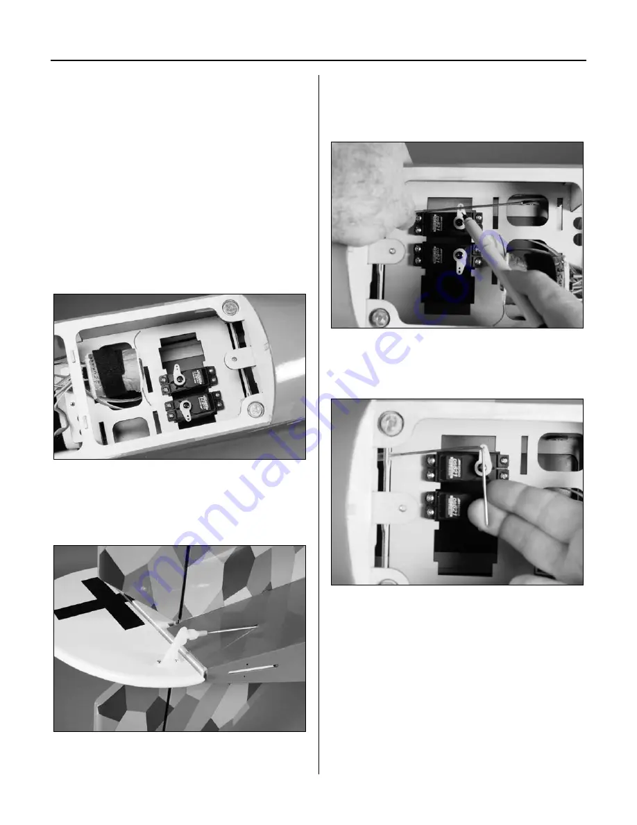
Step 4
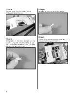
Use pliers to make a 90-degree bend in the rudder
pushrod as shown.
Note
: A piece of safety tubing has been
installed on the clevis. This will be placed over
the clevis once the control throws are set.
Section 6: Rudder and Elevator Linkage Installation
Summary of Contents for fokker D.VII
Page 53: ...53 Building and Flying Notes ...

