35
Hangar 9 Funtana 125 ARF Assembly Manual
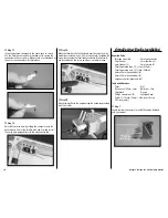
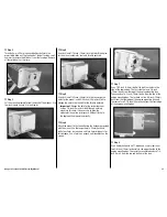
Step 2
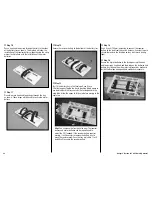
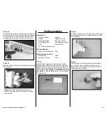
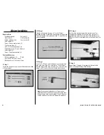
Thread a 4mm x 20mm hex head bolt partially into the
preinstalled blind nut. Tap the head of the bolt using a small
hammer to remove the blind nut from the fuselage. Remove
all four blind nuts at this time.
Step 3
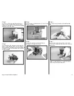
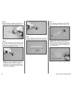
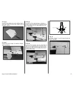
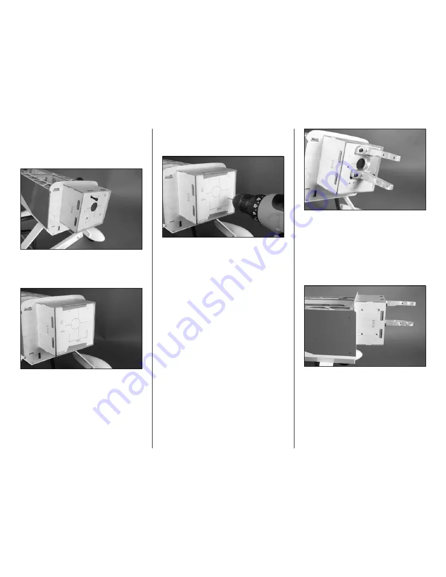
Cut the mounting template from the back of the manual. Use
low-tack tape to secure it to the firewall.
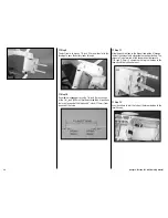
Step 4
Use a drill and 1/16-inch (1.5mm) drill bit to drill the holes
for the mount, carburetor vent and throttle pushrod.
Step 5
Use a drill and 7/32-inch (5.5mm) drill bit to enlarge the
holes for the mount, and a 9/64-inch (3.5mm) drill bit to
enlarge the hole in the firewall for the throttle pushrod.
Important
: Enlarge the hole for the carburetor vent
using a 1/4-inch (6mm) drill bit. Although nothing
mounts in this hole, it is necessary to allow the
carburetor to see true air pressure. Without this hole
the engine will not operate correctly.
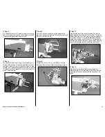
Step 6
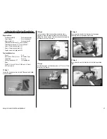
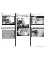
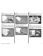
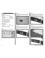
Attach the mount to the firewall using the hardware provided
with the mount. Use the longer 4mm x 20mm hex head
bolts, four 4mm star washers and four 4mm blind nuts for
this purpose. Use a 3mm hex wrench and threadlock on the
screws.
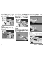
Step 7
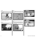
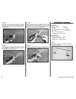
Use a 7/32-inch (5.5mm) drill bit to drill four holes in the
side of the engine box. The first set of holes is 3/4-inch
(19mm) down from the top of the engine mounting box.
The second set is 3-inch (76mm) down from the top of the
engine mounting box. The forward set are 3/4-inch (19mm)
back from the front edge of the engine mounting box, and
the rear set are 2-1/8-inch (54mm) back from the front edge
of the engine mounting box.
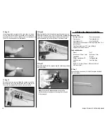
Step 8
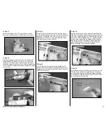
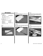
Use a hobby knife with a #11 blade and a rotary tool to cut
two 3/4-inch (19mm) wide slots in the opposite side of the
engine mounting box. These slots are centered and are 1/8-
inch (3mm) from the top and bottom of the box.

