46
Hangar 9 Funtana 125 ARF Assembly Manual
Elevator Installation
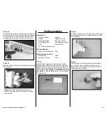
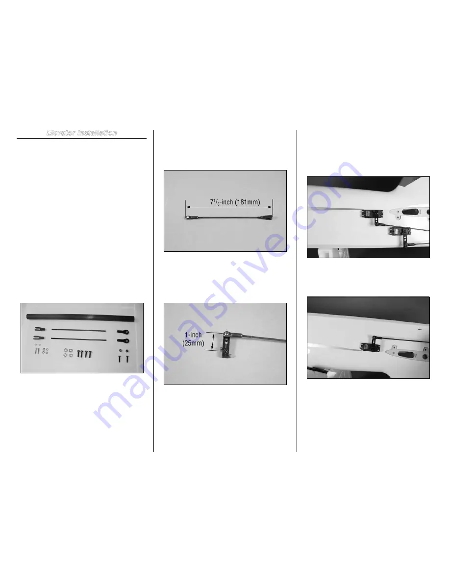
Required Parts
Fuselage assembly
Ball end (2)
Clevis end (2)
4-40 locknut (2)
Carbon stabilizer tube
2mm washer (2)
2mm locknut (2)
2mm x 12mm machine screw (2)
1-inch servo horn (2)
4-40 x 1/2-inch hex head bolt (2)
Threaded pushrod, 5
1
/
2
-inch (146mm)
3mm washer (4)
3mm x 12mm hex head bolt (4)
Tools and Adhesives
Phillips screwdriver: #1
Ruler
Hex wrench: 3/32-inch, 2.5mm
Nut driver: 4mm, 1/4-inch or 5.5mm
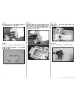
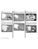
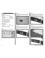
Step 1
Locate the items necessary to install the elevator included
with your model.
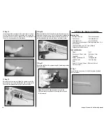
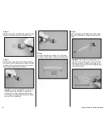
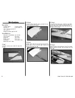
Step 2
Thread a ball end and clevis on a 5
1
/
2
-inch (146mm)
threaded pushrod. Thread both ends equally on the pushrod.
The overall length of the pushrod will be 7
1
/
8
-inch (181mm)
when assembled.
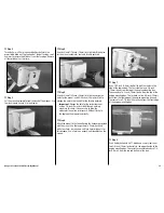
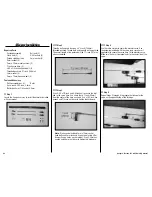
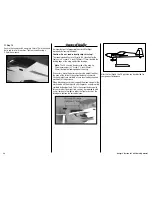
Step 3
Use a 4-40 x 1/2-inch and 4-40 locknut to secure the ball
end to the servo horn. Use a hole that is 1-inch (25mm)
from the center of the horn as shown. Use a 3/32-inch hex
wrench and 1/4-inch nut driver to tighten the hardware.
Note
: We have also included 3mm x 12mm socket
head bolts and 3mm locknuts if you are not using JR or
Hangar 9 servo horns on your model. Use a 2.5mm hex
wrench and 5.5mm nut driver to tighten this hardware.
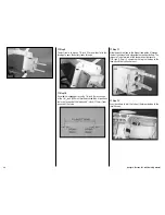
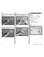
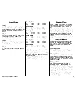
Step 4
Use the radio system to center the elevator servo. Use
the hardware included with the servo (and servo horn if
applicable) to secure the servo horn to the elevator servo.
Make sure the horn is perpendicular to the center line of the
servo.
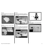
Step 5
Repeat Steps 2 through 4 to prepare the linkage for the
servo on the opposite side of the fuselage.

