30
Section 15 – Engine Installation
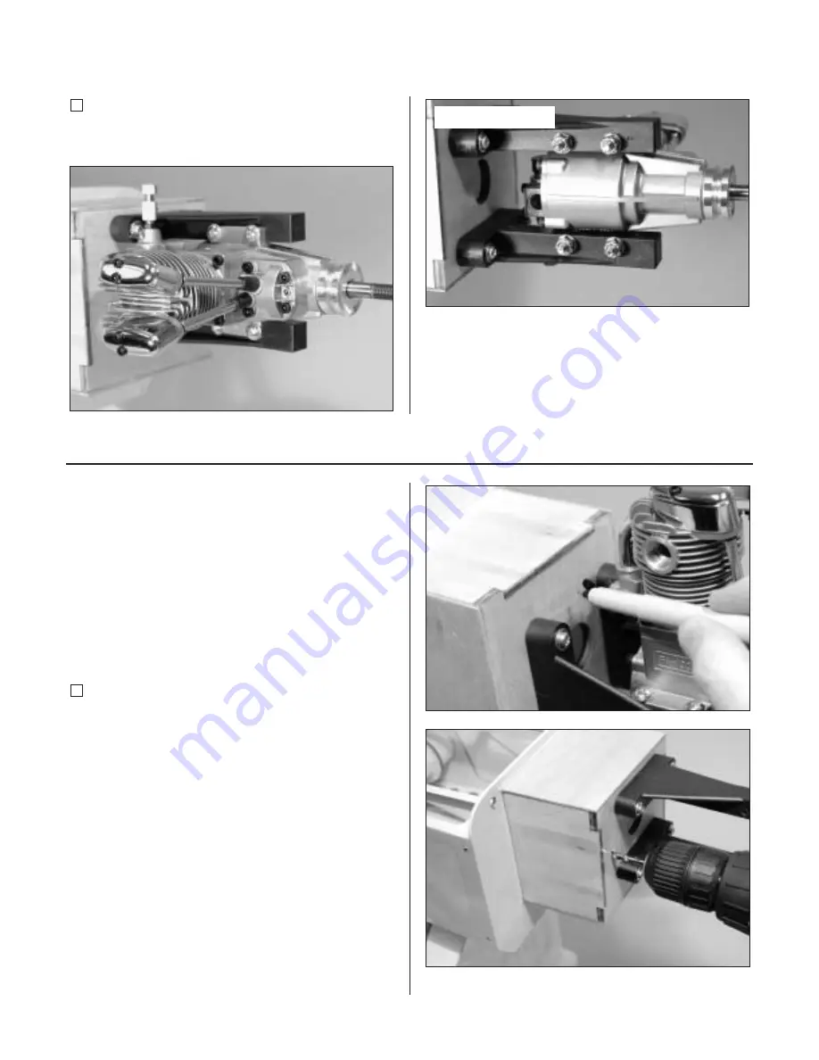
Step 5
Attach the engine using four 8-32 x 1-1/4" socket head
screws, eight #8 washers and four 8-32 lock nuts.
Section 16 – Throttle Pushrod Installation
Required Parts
• Clevis
• Clevis retainer
• Fuselage assembly
• 16
3
/
8
" outer pushrod tube
• 18
5
/
8
" pushrod wire
Required Tools and Adhesives
• Drill
• Drill bit: 5/32"
• Medium CA
• Sandpaper
Step 1
Determine the proper location for the throttle pushrod.
Mark the location with a felt-tipped pen. Remove the
engine and drill the firewall for the pushrod tube using a
drill and 5/32" drill bit.
Photo for Step 5


