Section 3 – Aileron Control Horn Installation
9
Required Parts
• Wing panel (left and right)
• Aileron (left and right)
• 4-40 x 1/2" screw (2)
• 4-40 lock nut (2)
• Tapered standoff (2)
• Threaded metal clevis (2)
• Clevis retainer (2)
• Nylon ball link (2)
• 4-40 x 2
3
/
4
" threaded rod (2)
• 4-40 nut (2)
• Nylon control horn (2)
• 2mm x 20mm self-tapping screw (6)
Required Tools and Adhesives
• Felt-tipped pen
• Threadlock
• Drill
• Drill bit: 1/16"
• Square
• Ruler
• Phillips screwdriver (small)
Step 1
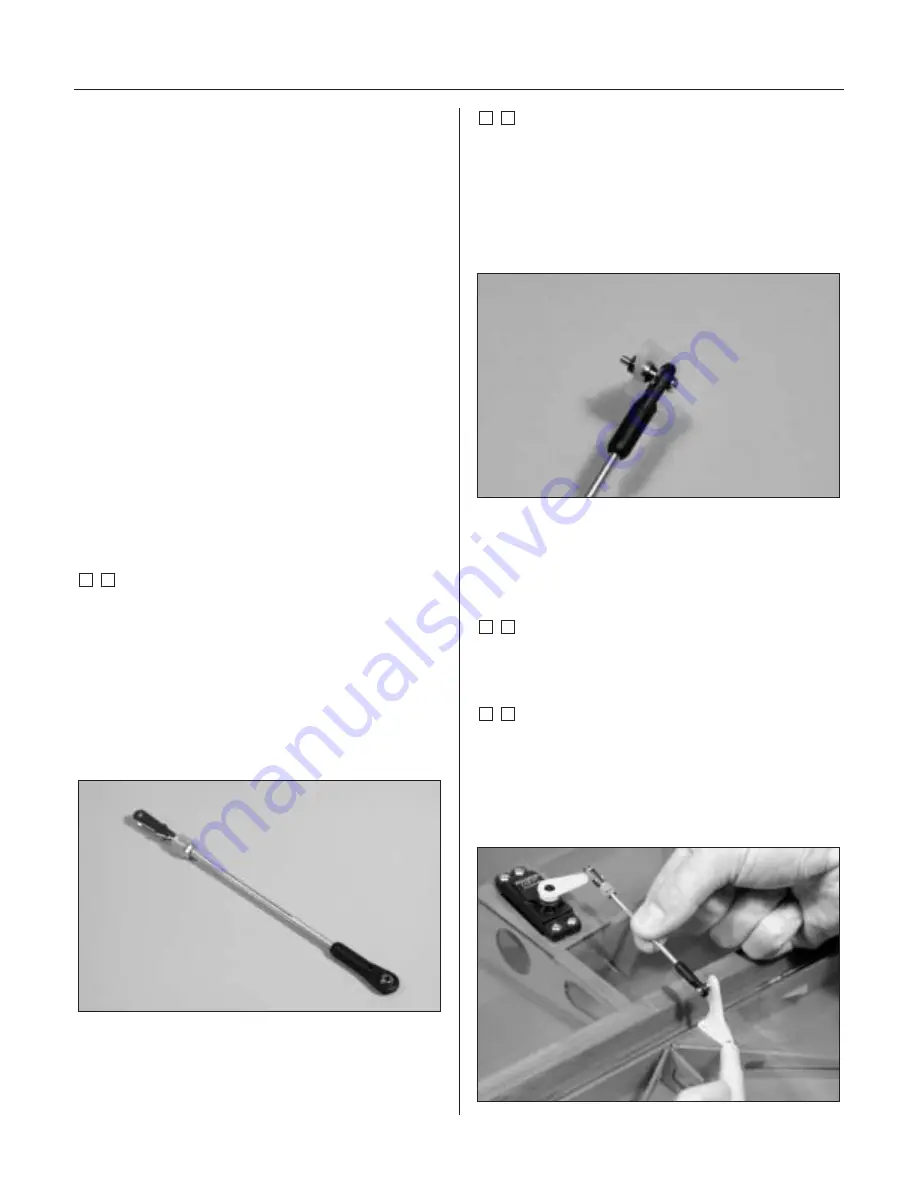
Locate the metal clevis 4-40 nut, clevis retainer and
nylon ball link. Thread the 4-40 nut onto one end of a 4-
40 x 2
3
/
4
" threaded rod. Slice a clevis retainer onto a
metal clevis and thread the clevis up against the nut. A
small amount of the rod will be visible between the forks
of the clevis. Tighten the nut against the clevis to prevent
it from loosening. Thread the nylon ball end onto the
other end of the threaded rod.
Note
: It is suggested that threadlock be used
on the nut and clevis to prevent them from
loosening during flight.
Step 2
Remove the backplate from one of the large control
horns. Attach the ball end to the center hole of the
control horn using a 4-40 x 1/2" screw, tapered standoff
and 4-40 lock nut. The standoff is positioned between
the ball end and control horn, which allows for smooth
operation of the linkage.
Note
: Attach the ball end so it will be
on the side of the control horn closest to
the wing tip.
Step 3
Attach a heavy-duty servo arm to the servo. Position the
arm parallel to the aileron hinge line.
Step 4
Position the control horn on the aileron so all three of the
mounting holes are centered on the mounting block. Also
check to make sure the linkage is at a 90-degree angle
to the servo arm. Transfer the location of the control
horn mounting holes onto the aileron.


