28
Step 7
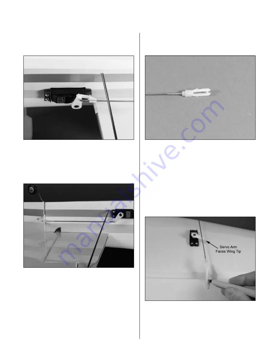
Slide the wire through the outer hole in the elevator
servo arm. Secure the wire using a nylon wire keeper.
Step 8
Repeat Steps 1 through 7 for the rudder linkage. Before
marking the location of the control horn, use the radio
to deflect the rudder servo to its full throw. The pushrod
will be parallel to the stabilizer for the correct geometry.
Step 9
Slide a clevis retainer onto a nylon clevis. Thread a clevis
onto a 7
7
/
8
" (200mm) wire a minimum of 10 turns.
Step 10
Remove the back plate from a control horn using side
cutters or a sharp hobby knife. Attach the clevis to
the control horn. After installing a heavy-duty servo
arm, position the control horn on the aileron so the
horn aligns with the hinge line of the aileron. With
the aileron servo deflected for full throw, position
the pushrod so it is perpendicular to the hinge line
as it crosses the servo arm. Mark the position for
the mounting holes using a felt-tipped pen.
Step 11
Drill three 1/16" (1.5mm) holes at the locations marked
in the previous step. The holes only need to be 3/4"
(19mm) deep: don’t drill through the top of the aileron.
Section 8: Servo Installation
Summary of Contents for FuntanaX 50
Page 33: ...33 Notes ...


