12
Hangar 9 Toledo Special Assembly Manual
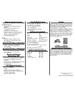
Step 9
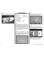
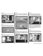
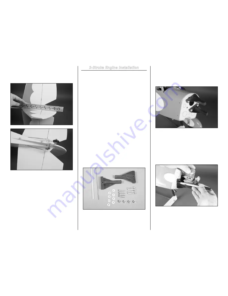
Repeat Step 8 to complete the installation of the rudder and
elevator linkages. Connect the clevis to the center hole of the
rudder control horn.
2-Stroke Engine Installation
Required Parts
Fuselage assembly
Motor mount (2)
#8 washer (8)
8-32 Lock nut (4)
Clevis
Clevis retainer
Engine
Pushrod keeper
Pushrod tube, 12-inch (305mm)
8-32 x 1-inch machine screw (4)
8-32 x 3/4-inch machine screw (4)
Throttle pushrod, 16
1
/
2
-inch (420mm)
Tools and Adhesives
Ruler
Threadlock
Phillips screwdriver: #1, #2 Felt-tipped pen
Medium grit sandpaper
Medium CA
Drill
Clamp
Drill bit: 5/64-inch (2mm), 5/32-inch (4mm)
Box wrench or nut driver: 11/32-inch
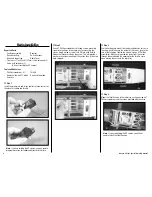
Step 1
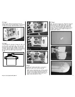
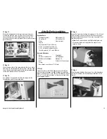
Locate the items to install the engine to your aircraft. You
will find these in the bags marked Pushrod Set and Motor
Mount. Set aside the four 1
7
/
8
-inch (48mm) EP standoffs and
the 8-32 x 2
1
/
4
-inch machine screws as they are not used
when installing glow engines.
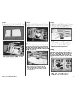
Step 2
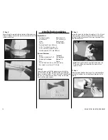
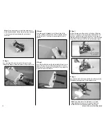
Secure the mounts to the firewall using four 8-32 x 3/4-inch
machine screws and four #8 washers. Make sure to place
a drop of threadlock on each of the screws to prevent them
from vibrating loose.
note
: Blind nuts have been installed for both glow and
EP versions. Make sure to position the mounts at an
angle as shown.
Step 3
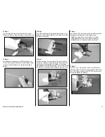
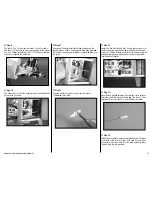
Slide the engine between the mounts. Use a felt-tipped pen
to mark the locations for the throttle pushrod tube on the
firewall.


