background image

USER MANUAL 

│ 

J1250

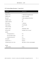
2.2 Technical Specifications - Control Unit

Functions

control unit

Specification

display screen

speed control

Max. RCF

ACC/DEC ramps

program memory

Time control

data transport

History tracking

Inverter control

Pump control

Safeties

Actual speed sensing

Door close/open sensing

Emergency Stop switch

foot switch

Level sensor 1, 2

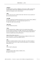
Dimensions (W x D x H mm)

7” wide touch (Capacitive type)

1,000 to 15,000 RPM

15,801 xg (Radius: 62.814 mm)

3/4

99

< 100 hours

Yes (USB port)

Yes

3P4W 380V, 7.5KW

Selectable, auto or manual

Yes

Yes

Yes

Optional

Optional

405x 460 x 1310 (incl. warning light)

Weight

without cables

47 kg

HANIL Scientific Inc. 

│ 

ihanil.com 

Service: +82-2-3452-8966 / techsupport@ihanil.com

11

Summary of Contents for J1250

Page 1: ...User Manual J1250 Continuous Tubular Centrifuge...

Page 2: ...up Gimpo si Gyeonggi do www ihanil com packaging unit 1 set including main body control unit and accessories The contents of the user manual are subject to change without notice HANIL Scientific Inc i...

Page 3: ...USER MANUAL J1250 HANIL Scientific Inc ihanil com Service 82 2 3452 8966 techsupport ihanil com 3...

Page 4: ...nd dimension 9 10 11 12 12 12 13 13 15 18 20 21 21 23 24 24 26 27 27 28 29 30 31 32 34 35 36 37 38 43 HANIL Scientific Inc ihanil com Service 82 2 3452 8966 techsupport ihanil com 4 3 Product installa...

Page 5: ...3 Bowl installation 5 4 Bowl and Motor Spindle fastening 5 5 Things to check before driving 5 6 Driving 44 44 45 46 48 48 50 52 53 54 54 54 55 55 57 6 Disassembly and maintenance 6 1 Disassembly 6 2...

Page 6: ...on by the user outside the range allowed by the device Before use be sure to check each part to make sure that there is no abnormality in the centrifuge In particular do not use the centrifuge that ha...

Page 7: ...bowl set that matches the serial number of the bowl attached to the front of the body see p8 The product installation site must be leveled and firmly fixed on a flat place Check that there is no prob...

Page 8: ...with the same Serial No for the best operation so never mix them The sticker shown on the right is attached to the outer surface of the main body and the Serial No Use bowl sets from xxxxxx Triangula...

Page 9: ...rocess time and increase productivity compared to general centrifugation methods Tubular type industrial centrifuge for continuous sample separation Two phase separation of liquid and solid High recov...

Page 10: ...eam base without pump or trolley Net Weight with bowl H beam base without pump or trolley 9 27 157 x 142 x 960 L mm Stainless Steel 316L Teflon with a dimension of 733x395x0 4 mm Peristaltic Tubing Pu...

Page 11: ...Actual speed sensing Door close open sensing Emergency Stop switch foot switch Level sensor 1 2 Dimensions W x D x H mm 7 wide touch Capacitive type 1 000 to 15 000 RPM 15 801 xg Radius 62 814 mm 3 4...

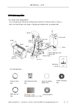
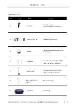
Page 12: ...with Motor control unit main unit Trolley Power Cable Bowl Hose Tube sample feeding pump Tube rack H beam base tool kit p15 17 filtrate tray Operation manual 2 3 2 Accessories Drag bushings 2ea Inlet...

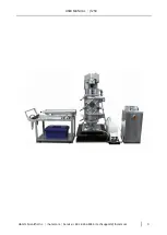
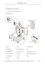
Page 13: ...rame 2 Motor 3 Drive motor cover 4 Pulley Flange 5 Drag Body Assembly 6 Door 6 1 water jacket door optional 7 Supernatant Outlet 8 Supernatant Outlet Lid 9 Balancing window 10 Base steel 11 Balancing...

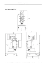
Page 14: ...USER MANUAL J1250 Main unit dimensions mm Front Right Left HANIL Scientific Inc ihanil com Service 82 2 3452 8966 techsupport ihanil com 14...

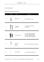
Page 15: ...l spindle assembly and disassembly 61mm for disassembling and assembling the pulley sleeve 54mm for disassembling and assembling the bearing pulley 3 2 Pulley wrenches Bowl boss sleeve wrench 4 Bow ca...

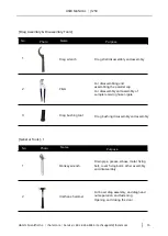
Page 16: ...3 Drag bushing tool Drag bushing disassembly and assembly General Tools 1 Drain pipe grease elbow motor fixing bolt cover fixing bolts other assembly and disassembly 1 Monkey wrench For bowl drag asse...

Page 17: ...n bowl cap nut and drag bushing 5 Grease For grease replenishment Teflon sheet and sludge separation 6 2 Specials For separating bowl and Teflon sheet For sludge separation 7 Bowl cleaner Bowl cleanin...

Page 18: ...ol available control mode Display 3 digit LED displays current speed Start stop cw ccw control speed control 4 to 20 mA 0 5 to 5 V 1 to 10 V 1 to 10 KHz external control power supply Power consumption...

Page 19: ...100 to 1 600 YZII15 13 14 19 16 25 17 18 4 to 2 200 YZII25 15 24 35 36 100 to 3 000 DG15 24 16 25 17 500 to 1 800 KZ25 15 24 35 36 200 to 6 000 When ordering a pump please order the pump head tubing...

Page 20: ...eration status indicator 7 Display LCD Screen Stop Running Green Alarm Red Yellow USB Port Imbal Door Foot RS232 Temp L1 L2 Ext conn Pump Conn Spare Conn Motor Cable Conn Power Cable Conn back side fr...

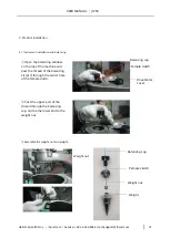
Page 21: ...the thread of the balancing kit p17 through the center hole of the female clutch Drive Motor Cover Pass the upper part of the thread through the balancing cap and tie the lower end to the weight nut A...

Page 22: ...d fix it Drive Motor Cover Bolt Adjust the height of the balancing foot so that the vertex of the weight is located at the center of the nozzle hole Nozzle hole Base Balancing foot Drag body Assembly...

Page 23: ...wiring and connection status once more Connect the power cable between the external terminal box and the control unit Organize the product and surrounding facilities After checking the input power an...

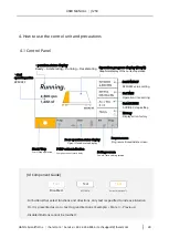
Page 24: ...Door operation status display Open Closed status display Program screen Program call save delete screen Start Stop Start Stop operation PUMP action indication Pump operation status display Settings sc...

Page 25: ...is displayed and the icon is activated during operation The basic operation is that when the set RPM is reached the pump automatically turns on and runs and stops when it stops In case of manual contr...

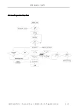
Page 26: ...USER MANUAL J1250 4 2 Overall operation flow chart HANIL Scientific Inc ihanil com Service 82 2 3452 8966 techsupport ihanil com 26...

Page 27: ...displayed in RPM RCF and the maximum RPM is 15 000 and the maximum RCF is 15 801 xg RCF values for RPM are automatically calculated in conjunction with each other 1 Press Set Speed at the top right o...

Page 28: ...en touched the last input digit is erased Touch to complete input mode Cancels the entered settings and restores the previous settings Displays the set time value When entering time setting the input...

Page 29: ...numeric keypad is touched the setting value is changed When touched the last input digit is erased Touch to complete input mode Cancels the entered settings and restores the previous settings Display...

Page 30: ...and hold to quickly scroll down the page Put the list up one page Press and hold to speed up the page Button to copy History Data to USB storage device If the USB storage device is not connected or th...

Page 31: ...hen connecting via USB Pop up generated by Raspberry pi system cancel it 2 SAVE If USB is connected and there is History Data to be saved the button is activated When History Data copy to USB is compl...

Page 32: ...me saved on and the last called time last used on Scroll down the list by one page Press and hold to quickly scroll down the page Upload the list by one page Press and hold to speed up the page Load t...

Page 33: ...1 2 CANCEL Return to the previous screen OK Load the saved program and apply the settings to the main screen CANCEL Return to the previous screen OK Save the current setting value in the selected prog...

Page 34: ...SER MANUAL J1250 4 10 Start Stop It can be used to start or stop motion Standby Status Screen In operation Status screen HANIL Scientific Inc ihanil com Service 82 2 3452 8966 techsupport ihanil com 3...

Page 35: ...Message ok Title of Message Box is displayed The contents of the Message Box are displayed When the ok button is touched the Message Box disappears In case of emergency stop the message box is displa...

Page 36: ...ed on off manually during operation 1 1 PUMP PUMP action Image PUMP ON PUMP OFF When the set RPM is reached the PUMP turns ON RUN automatically In the section where deceleration starts PUMP is automat...

Page 37: ...display screen 1 2 3 1 2 3 Title Message OK The Title of the Message Box is displayed The contents of the Message Box are displayed When the OK button is touched the Message Box disappears HANIL Scie...

Page 38: ...his is the screen where you can set items 1 2 1 2 Back button Menu When touched it moves to the Main screen Enter the selected menu HANIL Scientific Inc ihanil com Service 82 2 3452 8966 techsupport i...

Page 39: ...Off When the Switch button is clicked it is changed to Off Each time the button is touched the volume is changed When touched it moves to the Setting screen Volume setting You can set a value between...

Page 40: ...ayed Displays the current system time Apply the set time to the system The set time zone is applied to the system UP DOWN Date In the case of February if the date cannot be set it is automatically cha...

Page 41: ...es to the Setting screen Displays the Model Name Displays the description of the Model Displays the version Main Display Displays centrifuge operation information Cycle Count Displays Count for centri...

Page 42: ...d If the update program is not confirmed it will be deactivated Close the UPDATE Message Box Proceed with the UPDATE procedure Update Program 1 Update is performed through USB 2 The program should be...

Page 43: ...and contents are displayed When the OK button is touched the Message Box disappears The Error Message Box appears on any screen Error Message Box When an error occurs in the centrifuge an Error Messa...

Page 44: ...1250 5 Preparing and How to Drive 5 1 Bowl assembly Bowl Top Bowl body Teflon sheet Triangular rotor blades Tension spring Bowl cap HANIL Scientific Inc ihanil com Service 82 2 3452 8966 techsupport i...

Page 45: ...factured and supplied according to the inner diameter of the bowl so you can use it as it is Insert so that the front side is the sample contact area Place the bowl on the trolley fold the Teflon shee...

Page 46: ...s positioned in front Bowl cap Tension spring Insert carefully so that the tip of the wing does not touch the interlocking part of the Teflon sheet Teflon sheet Hold the upper end of the bowl and inse...

Page 47: ...during operation When removing the bowl cap check that the bowl cap sealing gasket is fixed as previously inserted After tightening the bowl wrench to match the center of the bowl fully tighten it us...

Page 48: ...assemble it by fastening the drag hand nut The inlet nozzle is installed with 3 by default and it is replaced after testing with 4 or 5 inlet nozzles depending on the solid size of the sample or the...

Page 49: ...otor Cover body frame Supernatant Outlet Insert the Supernatant Outlet lid into the Supernatant Outlet inner diameter groove Drive Motor Cover Drive Motor Cover Supernatant Outlet lid Supernatant Outl...

Page 50: ...spindle and bowl It is fastened with the bowl and rotates Pulley Flange Spindle Bowl top Supernatant Outlet Supernatant Outlet lid Fasten the seated spindle and the top of the bowl in a clockwise dire...

Page 51: ...he spindle protective sleeve screwed inside the pulley flange counterclockwise to fix the Supernatant Outlet lid so that it does not move Pulley Flange Spindle protective sleeve HANIL Scientific Inc i...

Page 52: ...n the spindle protective sleeve and tighten it as much as possible see p51 Connect the Sample in tube to the sample inlet and connect it to the sample bottle through the pump head of the sample feedin...

Page 53: ...ts the sample separation operation Stop is automatically stopped when the set time has elapsed However it is not allowed to stop while the sample is being fed so the motor must be stopped after stoppi...

Page 54: ...wise Turn the drag handle counterclockwise using a urethane hammer Hold the lower part of the drag body and turn it counterclockwise and then separate it from the lower part of the body 6 2 Cleaning U...

Page 55: ...to thoroughly clean the bowl every time the operation is stopped so that no solids remain in the bowl Always use the provided tool to clean the surface of the spindle connection part coupling nut of t...

Page 56: ...g that the rubber coupling is in close contact with the inside of the pulley cap replace it immediately if it is cracked or damaged Remove and replace cracked or damaged rubber coupling inside the pul...

Page 57: ...ces around the equipment and check the motor fan operation ERR 7 Control unit error This is a system error in the control unit After replacing the control unit check again ERR 9 RPM Sensing error It o...

Page 58: ...unit Stainless Steel with Water Jacket for J1250 J1250SSWJ BOWL Stainless Steel with a Trolley Stainless Steel and Teflon sheet 3ea BW9 TS J CTS 380 7 Controller unit with 7 LCD and Inverter for 380V...

Page 59: ...USER MANUAL J1250 HANIL Scientific Inc ihanil com Service 82 2 3452 8966 techsupport ihanil com 59 MEMO...

Page 60: ...Hanil Scientific HANIL Scientific Inc 16 Arayuk ro Gochon eup Gimpo si Gyeonggi do ihanil com 2022 Hanil Scientific Inc All rights reserved...

Reviews: