8
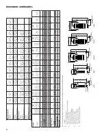
Standar
d and CR
HF (Grade)-
52-24
52-24-D
(2)
54-24
56-24
60-24
64-4F
68-4F
72-6F
76-6F
80-6F
84-8F
88-8F
92-10F
Connection
3” NPT
3” NPT
3” NPT
3” NPT
3” NPT
4” ANSI Flg.
4” ANSI Flg.
6” ANSI Flg.
6” ANSI Flg.
6” ANSI Flg.
8”ANSI Flg.
8”ANSI Flg.
10”ANSI Flg.
Maximum W
orking Pressure
300 psig
300 psig
225 psig
225 psig
225 psig
225 psig
225 psig
225 psig
225 psig
225 psig
225 psig
225 psig
225 psig
HF (Grade)-
52-80
52-80-D
(2)
54-80
56-80
60-80
64-100
68-100
72-150
76-150
80-150
84-200
88-200
92-250
Connection
DN 80 Flg.
DN 80 Flg.
DN 80 Flg.
DN 80 Flg.
DN 80 Flg.
DN 100 Flg.
DN 100 Flg.
DN 150 Flg.
DN 150 Flg.
DN 150 Flg.
DN 200 Flg.
DN 200 Flg.
DN 250 Flg.
Maximum W
orking Pressure
21.0 kgf/cm
2
21.0 kgf/cm
2
15.8 kgf/cm
2
15.8 kgf/cm
2
15.8 kgf/cm
2
15.8 kgf/cm
2
15.8 kgf/cm
2
15.8 kgf/cm
2
15.8 kgf/cm
2
15.8 kgf/cm
2
15.8 kgf/cm
2
15.8 kgf/cm
2
15.8 kgf/cm
2
High Pressure
HF (Grade)-
52-24-34
52-24-34-D
52-24-48
54-24-31
56-24-31
60-24-45
64-4F-30
68-4F-30
72-6F-24
76-6F-22
80-6F-22
84-8F-18
Connection
3” NPT
3” NPT
3” NPT
3” NPT
3” NPT
3” NPT
4” ANSI Flg.
4” ANSI Flg.
6” ANSI Flg.
6” ANSI Flg.
6” ANSI Flg.
8”ANSI Flg.
Maximum W
orking Pressure
500 psig
500 psig
700 psig
450 psig
450 psig
650 psig
440 psig
440 psig
360 psig
330 psig
330 psig
260 psig
HF (Grade)-
52-80-34
52-80-34-D
52-80-48
54-80-31
56-80-31
60-80-45
64-100-30
68-100-30
72-150-24
76-150-22
80-150-22
84-200-18
Connection
DN 80 Flg.
DN 80 Flg.
DN 80 Flg.
DN 80 Flg.
DN 80 Flg.
DN 80 Flg.
DN 100 Flg.
DN 100 Flg.
DN 150 Flg.
DN 150 Flg.
DN 150 Flg.
DN 200 Flg.
Maximum W
orking Pressure
35.0 kgf/cm
2
35.0 kgf/cm
2
49.0 kgf/cm
2
31.5 kgf/cm
2
31.5 kgf/cm
2
45.0 kgf/cm
2
30.8 kgf/cm
2
30.8 kgf/cm
2
25.2 kgf/cm
2
23.1 kgf/cm
2
23.1 kgf/cm
2
18.2 kgf/cm
2
No. of Elements E(Grade)-PV or PVS
1
1
1
2 (1)
2
3
4
5
8
11
14
19
26
34
Models
HP
HP
HP
HP
HP
HP
HP
HP
CF (Grade)-
52-24(5) 52-24-D(2) 52-80(5) 52-80-D(2)
52-24-34
52-24-34-D(2)
52-80-34
52-80-34-D(2)
52-24-48 52-80-48
54-24-31 54-80-31 56-24-31 56-80-31
54-24 54-80 56-24(5) 56-80(5)
60-24(5) 60-89(5)
60-24-45 60-80-45
64-4F(5) 64-100(5) 68-4F(5) 68-100(5)
64-4F-30 64-100-30 68-4F-30 68-100-30
72-6F 72-150
72-6F-24 72-150-24
76-6F 76-150 80-6F 80-150
76-6F-22 76-150-22 80-6F-22 80-150-22
84-8F 84-200
84-8F-18 84-200-18
88-8F 88-200
92-10F 92-250
Dimensions in (mm)
“A” w/thread
10.25 (260)
10.25 (260)
10.25 (260)
20.00 (508)
16.00 (406)
16.25 (413)
16.25 (413)
—
—
—
—
—
—
—
—
—
—
“A” w/flange
10.63 (270)
11.63 (295)
11.00 (279)
21.38 (543)
16.38 (416)
16.63 (423)
17.63 (448)
20.00 (508)
20.00 (508)
24.00 (610)
24.00 (610)
28.00 (711)
28.00 (711)
33.00 (838)
33.00 (838)
39.00 (991)
45.88 (1165)
“B”
40.88 (1038)
42.38 (1076)
40.44 (1027)
50.44 (1281)
48.00 (1219)
49.00 (1245)
55.50 (1410)
52.25 (1327)
55.50 (1410)
54.63 (1387)
55.88 (1419)
62.56 (1589)
63.88 (1622)
69.13 (1589)
66.25 (1683)
67.94 (1726)
70.94 (1802)
“C”
4.88 (124)
4.88 (124)
8.31 (211)
10.81 (275)
9.69 (246)
9.69 (246)
11.69 (297)
11.63 (295)
12.69 (322)
13.44 (341)
14.69 (373)
16.88 (429)
18.19 (462)
19.63 (498)
19.69 (500)
19.56 (497)
21.56 (548)
“D”
32.25 (819)
32.25 (819)
29.5 (749)
39.63 (1006)
38.31 (973)
39.31 (99)
40.50 (1029)
40.63 (1032)
40.56 (1030)
41.19 (1046)
39.44 (1002)
45.69 (1160)
43.44 (1103)
49.50 (1257)
44.31 (1126)
48.38 (1229)
49.38 (1254)
W
eight lb (kg)
w/thread
36 (16)
39 (17)
128 (58)
270 (123)
90 (41)
118 (54)
294 (133)
—
—
—
—
—
—
—
—
—
—
w/flange
52 (23)
65 (29)
154 (70)
296 (135)
106 (48)
134 (61)
320 (145)
(3)
(3)
271 (123)
524 (238)
(4)
(4)
709 (322)
980 (445)
918 (416)
1412 (640)
Drain Connection
1/2”
1/4”
3/4”
1”
1”
1”
1”
1”
1”
1”
1”
1”
1”
1”
1”
1”
1”
V
essel T
ype
I
I
II
III
IV
IV
III
IV
V
IV
V
IV
V
IV
V
IV
IV
NOTE: Dimensions and W
eights are for reference only
. Request certified drawings for construction purposes.
(
1)
E(Grade)-54
(2)
D signifies internal auto drain.
Add 1.5 in. (38mm) to dim. B and 3 lb (1.4 kg) to weight.
(3)
64-4F and 64-100: 178 (81);
68-4F and 68-100: 180 (82);
64-4F-30 and 64-100-30: 408 (183);
68-4F-30 and 68-100-30: 405 (184)
(4)
76-6F and 76-150: 518 (235);
80-6F and 80-150: 525 (238);
76-6F-22 and 76-150-22: 693 (314);
80-6F-22 and 80-150-22: 700 (318)
(5)
Includes Corrosion Resistant (CR) Models
Dimensions and Weights
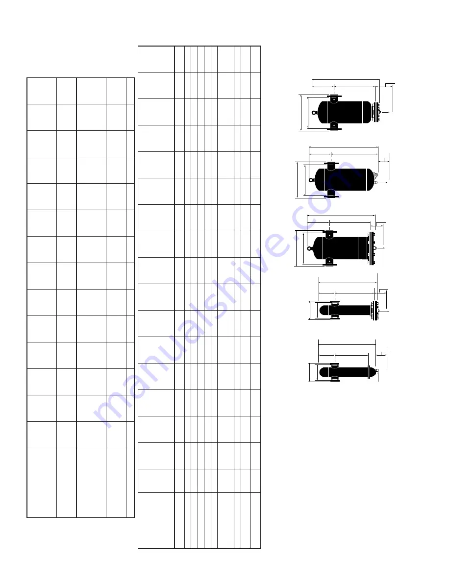
SERVICE CLEARANCE 24" (610mm)
DRAIN
D
B
C
A
TYPE II
SERVICE CLEARANCE 24" (610mm)
DRAIN
D
B
C
A
TYPE V
SERVICE CLEARANCE 24" (610mm)
DRAIN
D
B
C
A
TYPE IV
A w/Flg.
A
Optional Internal Auto Drain
SERVICE CLEARANCE 24" (610mm)
D
B
C
A w/Flg.
A
DRAIN
SERVICE CLEARANCE 24" (610mm)
D
B
C
A w/Flg.
A w/Flg.
A w/Flg.
TYPE I
TYPE III

