background image

23

METER INITIALIZA

TION

After connecting the desired sensors to the probe and connecting the probe to the meter (see previous 
chapter), turn the meter on by pressing 

On/Off 

key.

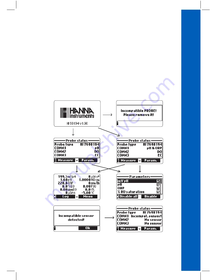
After the initialization has been completed if the probe is connected, the meter displays the  
PROBE STATUS SCREEN. The probe status screen identifies the probe and attached sensors. If an 
incompatible probe was connected the following message appears and the probe has to be replaced. 
The compatible meter‑probe pairs are: 

HI98194 ‑ HI7698194; HI98195 ‑ HI7698195;

HI98196 ‑ HI7698196.

If an incompatible sensor was connected to the probe, “Incompat.sensor!” will be displayed  
according to the respective connector. If the sensor was placed in a wrong connector, “Wrong input” 
will be displayed for that connector.

Summary of Contents for HI98194

Page 1: ...HI98194 HI98195 HI98196 Multiparameter Meters pH mV ORP EC TDS Resistivity Salinity Seawater σ Dissolved Oxygen Atmospheric Pressure and Temperature INSTRUCTION MANUAL ...

Page 2: ... instrument as well as a precise idea of its versatility If you need additional technical information do not hesitate to e mail us at tech hannainst com or view our worldwide contact list at www hannainst com Dear Customer All rights are reserved Reproduction in whole or in part is prohibited without the written consent of the copyright owner Hanna Instruments Inc Woonsocket Rhode Island 02895 USA...

Page 3: ...tallation Basic Operation Help Function CHAPTER 3 SPECIFICATIONS System Specifications Probe Specifications Sensor Specifications CHAPTER 4 PROBE INSTALLATION Sensor Descriptions Sensor Preparation Activation Sensor Installation CHAPTER 5 INITIALIZATION AND MEASUREMENT Battery Installation Meter Initialization Measurement Mode Setup Menu Structure CHAPTER 6 PARAMETER SETUP MENU Select Parameters P...

Page 4: ...HI98194 HI98195 only Temperature Calibration Atmospheric Pressure Calibration CHAPTER 8 SYSTEM SETUP Meter Setup Probe Setup CHAPTER 9 STATUS Meter Status Probe Status GLP Data CHAPTER 10 LOGGING MODE Logging Mode Logging Menu Structure Logging On Meter Log Recall Log Notes CHAPTER 11 PC CONNECTION PC Connection CHAPTER 12 TROUBLESHOOTING ERROR MESSAGES Troubleshooting Error Messages APPENDIX A PR...

Page 5: ... Quick Reference Guide Certificate Note Save all packing materials until you are sure that the instrument functions correctly Any damaged or defective items must be returned in their original packing material with the supplied accessories Chapter 1 INTRODUCTION PRELIMINARY EXAMINATION MODEL IDENTIFICATION HI98194 pH mV ORP EC TDS Resistivity Salinity Seawater σ Dissolved Oxygen Atmospheric Pressur...

Page 6: ...IP67 standards 30 minute immersion at a depth of 1 m and the multisensor probe meets IP68 standards continuous immersion in water Main features of the HI9819X systems Rugged meter and probe Easy to use Measure up to 14 parameters and display of up to 12 parameters Waterproof protection IP67 for the meter and IP68 for the probe Graphic LCD with backlight Built in barometer for D O concentration com...

Page 7: ...urn the meter on and off 5 Lamp key turn the backlight on and off 6 Alphanumeric keyboard insert alphanumeric codes 7 Arrow keys scroll the displayed options message 8 HELP key obtain information about the displayed screen 9 ESC key return to the previous screen 10 Softkey functions defined on display ...

Page 8: ...of the probe make sure the connector is seated correctly the sensor will no longer move freely before tightening the locking threads To protect the sensors screw the protective shield onto the probe body With the meter off connect the probe to the instrument input on the top of the meter Align the pins and key then push the plug into the socket and tighten the thread Turn the meter on by pressing ...

Page 9: ...9 SENSOR AND PROBE INSTALLATION ...

Page 10: ... blink when the reading is out of range Press Log to display the logging menu You can either log a single sample on the meter or start an interval log on the meter See Chapter 10 for more details Press Menu to enter setup mode You can configure which parameters you want to measure calibrate the sensors change system settings and view the meter and probe status HELP FUNCTION HI9819X features contex...

Page 11: ...1 9 18 10 01 and 1 custom buffer ORP Range 2000 0 mV Resolution 0 1 mV Accuracy 1 0 mV Calibration Automatic at 1 custom point relative mV DISSOLVED OXYGEN HI98194 HI98196 only Range 0 0 to 500 0 0 00 to 50 00 ppm mg L Resolution 0 1 0 01 ppm mg L Accuracy 0 0 to 300 0 1 5 of reading or 1 0 whichever is greater 300 0 to 500 0 3 of reading 0 00 to 30 00 ppm mg L 1 5 of reading or 0 10 ppm mg L whic...

Page 12: ...SISTIVITY HI98194 HI98195 only Range 0 to 999999 Ω cm 0 to 1000 0 kΩ cm 0 to 1 0000 MΩ cm Resolution Depending on resistivity reading Calibration Based on conductivity or salinity calibration TDS Total Dissolved Solids HI98194 HI98195 only Range 0 to 400000 ppm mg L the maximum value depends on the TDS factor Resolution Manual 1 ppm mg L 0 001 ppt g L 0 01 ppt g L 0 1 ppt g L 1 ppt g L Automatic 1...

Page 13: ...95 only Range 0 0 to 50 0 σt σ0 σ15 Resolution 0 1 σt σ0 σ15 Accuracy 1 0 σt σ0 σ15 Calibration Based on conductivity or salinity calibration ATMOSPHERIC PRESSURE Range 450 0 to 850 0 mmHg 17 72 to 33 46 inHg 600 0 to 1133 2 mbar 8 702 to 16 436 psi 0 5921 to 1 1184 atm 60 00 to 113 32 kPa Resolution 0 1 mmHg 0 01 in Hg 0 1 mbar 0 001 psi 0 0001 atm 0 01 kPa Accuracy 3 0 mmHg within 15 C from cali...

Page 14: ... mm 7 3 x 3 6 x 1 4 400 g 14 2 oz METER BATTERY LIFE The power consumption of the HI9819X multiparameter systems are dependent on two things 1 The measurement system configuration sensor configuration 2 The meter configuration logging interval and backlight use The following table estimates the meter s battery life connected to a HI769819X probe with backlight off Note Backlighting use consume the...

Page 15: ...rature 20 to 70 C Maximum Depth 20 m 66 Dimensions without cable 342 mm 13 5 dia 46 mm 1 8 Weight with batteries and sensors 570 g 20 1 oz Cable Specification Multistrand multiconductor shielded cable with internal strength member rated for 68 kg 150 lb intermittent use Wetted Materials Body ABS Threads Nylon Shield ABS 316 SS Temp probe 316 SS O Rings EPDM PROBE SPECIFICATIONS ...

Page 16: ...C 5 to 55 C 5 to 55 C 5 to 55 C Color Code Red Red White Blue Materials Tip glass pH Junction ceramic Body PEI Electrolyte gel Reference double Tip glass pH Pt ORP Junction ceramic Body PEI Electrolyte gel Reference double Cat An Ag Zn Membrane HDPE Body whitetopABS CAP Stainless steel electrodesAISI316 Body ABS EPOXY Maintenance Solution HI70300 storage solution HI70300 storage solution HI7042S D...

Page 17: ...aration See page 18 for ORP activation HI7698194 2 Galvanic dissolved oxygen D O sensor The thin gas permeable membrane isolates the sensor elements from the testing solution but allows oxygen to pass through The oxygen that passes through the membrane is reduced at the cathode and causes a current from which the oxygen concentration is determined The D O sensor conforms to Standard Methods 4500 A...

Page 18: ...ecessary pH mV pH mV pH mV pH mV pH mV 0 990 1 920 2 860 3 800 4 740 5 680 6 640 7 580 8 520 9 460 10 400 11 340 12 280 13 220 14 160 For reducing pretreatment immerse the electrode for at least five minutes in HI7091 For oxidizing pretreatment immerse the electrode for at least five minutes in HI7092 D O Sensor Activation The D O probe is shipped dry To prepare the sensor for use Remove the black...

Page 19: ...o clean and loosen any debris before using SENSOR INSTALLATION The HI7698194 can support three different sensors Connector 1 pH pH ORP Connector 2 D O Connector 3 EC To make installation easier the sensors have color coded caps and the sockets are identified with colored triangles corresponding to the colors of the sensors pH red EC blue D O white ...

Page 20: ...20 The HI7698195 support two different sensors Connector 1 pH pH ORP Connector 2 EC The HI7698196 support two different sensors Connector 1 pH pH ORP Connector 2 D O SENSOR INSTALLATION ...

Page 21: ... threads with the tool supplied in the maintenance kit until the sensor is secured tightly against the probe body To protect the sensors screw the protective shield onto the probe body With the meter off connect the probe to the DIN socket on the bottom of the meter Align the pins and key then push the plug into the socket Secure the probe by attaching the carabinier of the probe to the meter pist...

Page 22: ...tery warning and when the symbol starts blinking batteries should be replaced with new ones When the batteries are discharged the meter will automatically shut off to avoid erroneous readings Replace batteries in safe areas only Remove the 4 screws on the rear of the instrument and insert the batteries observing polarity Note Do not mix old and new alkaline batteries BATTERY INSTALLATION ...

Page 23: ...REEN The probe status screen identifies the probe and attached sensors If an incompatible probe was connected the following message appears and the probe has to be replaced The compatible meter probe pairs are HI98194 HI7698194 HI98195 HI7698195 HI98196 HI7698196 If an incompatible sensor was connected to the probe Incompat sensor will be displayed according to the respective connector If the sens...

Page 24: ...sure data for all enabled parameters Use the numbers on the keyboard to select the number of parameters that are shown on the screen at one time The display will automatically resize the font Press the keys to scroll through the enabled parameters if they do not fit on one screen Notes A flashing measurement value indicates that the measurement is out of range A flashing measurement unit indicates...

Page 25: ...25 SETUP MENU STRUCTURE ...

Page 26: ...Note If the password protection is enabled you will be required to enter the password before any parameters can be modified Temperature Unit The user can select the measurement unit C F or K The default value is C TDS Unit HI98194 HI98195 only The user can select ppm ppt or mg L g L measurement unit The default value is ppm ppt D O Concentration Unit HI98194 HI98196 only The user can select ppm or...

Page 27: ...the range to optimize the measurement readings will be in mS cm only 1μS cm 0 001 mS cm 0 01mS cm 0 1mS cm or 1mS cm the meter will not autorange the measurement will be displayed with the selected resolution The default value is Auto Absolute EC Resolution Unit HI98194 HI98195 only Absolute conductivity displays the conductivity without temperature compensation See EC resolution for resolution de...

Page 28: ...00 C The default value is 1 90 C TDS Factor HI98194 HI98195 only TDS stands for total dissolved solids and it is a calculated value based on the conductivity of the solution TDS factor x EC25 The TDS conversion factor can be set from 0 00 to 1 00 A typical TDS factor for strong ionic solutions is 0 50 while for weak ionic solutions e g fertilizers is 0 70 Press Modify to enter the value press Acce...

Page 29: ...lish the optimum calibration period required for the measurement environment Calibration requirements vary with deployment conditions for example very turbid biologically active waters may require more frequent cleanings and calibrations than cleaner waters General calibration guidelines are listed below Set up a routine service schedule where measurement integrity is validated This is especially ...

Page 30: ... store the calibration data The Storing message will appear as the calibration proceeds to the next sensor A checkmark will appear in the box next to pH to indicate a successful calibration Notes To bypass any of the calibrations press Skip to move to the next sensor in the quick calibration menu If the pH sensor is not installed the message pH sensor not installed Skip to conductivity calibration...

Page 31: ...play shows two options Calibrate pH and Restore factory calib If a new pH sensor has been installed use Restore factory calib before performing a user calibration as some warning messages are based on changes from previous calibrations If Restore factory calib is selected all user calibration data will be deleted and the default calibration is restored A user calibration should follow immediately ...

Page 32: ...tion and stir gently Press Cal Point to select the next buffer if necessary and repeat the calibration procedure outlined above with the second and third buffers Note The calibration procedure can be terminated after a single or 2 point calibration by pressing ESC The message Storing followed by Calibration completed will be displayed Press OK to return to the Calibration menu Press Measure to ret...

Page 33: ...fer value This is often seen immediately after a buffer calibration has been completed but before the pH sensor has been moved to the next buffer Check if the correct calibration buffer has been selected Invalid temperature the buffer temperature is outside the acceptable range Wrong buffer Contaminated buffer Check electrode the buffer is contaminated or the sensor is broken or very dirty Check s...

Page 34: ...n well poised solutions standards for example but may be more lengthy in natural water samples Calibration is typically not required for a new ORP sensor but the process does establish a baseline that can be used as a comparison for future validations Calibration is used to compensate for changes due to contamination of the platinum surface and drift in the reference electrode A relative mV calibr...

Page 35: ...ved oxygen measurements is directly related to membrane cleanliness and calibration technique Oily coating and biological contaminants are the primary cause of calibration drift in dissolved oxygen sensors Unfortunately brushes or other cleaning objects may damage the membrane Replacing the membrane cap and electrolyte is the best way to perform periodic maintenance Although it may be easier to ca...

Page 36: ...e reading temperature calibration point and the Not ready message are displayed Once the reading has stabilized the countdown timer will count down until the display shows the Ready message Press Confirm to accept the calibration point After confirmation put the D O and temperature sensors into HI7040 zero oxygen solution and wait for stability to be reached The stability timer will count down and...

Page 37: ...I98196 only Verify the barometric pressure conductivity and temperature reading are correct Calibrate them if necessary To calibrate the D O concentrationrange asolutionwithknowndissolvedoxygen concentration value is needed The solutions used to calibrate with should be determined independently for instance by Winkler titration Place the D O sensor with temperature sensor into the known solution F...

Page 38: ...libration menu includes 3 different types of calibration Conductivity Absolute conductivity and Salinity The Conductivity option allows a single point calibra tion with a standard solution selectable by the user This calibration is temperature compensated The Absolute conductivity option allows a single point calibration with a conductivity solution of known non temperature compensated value at th...

Page 39: ...ing the keypad then press Accept When the reading becomes stable the stability timer will count down and Confirm will appear Press Confirm to save the calibration After confirmation the following messages are displayed Storing and Calibration completed Press OK to return to the Calibration menu Press ESC twice to return to main menu Press Measure to return to the measurement screen Absolute Conduc...

Page 40: ...ation menu Use the keypad to enter the known salinity value of the calibra tion solution Press Accept to confirm Fill the calibration beaker with salinity standard of known value Pour additional standard into a second beaker to be used to rinse the sensor Immerse the sensor into the rinse beaker and raise and lower the beaker to ensure that the EC sensor channels are filled with fresh standard Pla...

Page 41: ...e measuring instrument Select Temperature from the Calibration menu Select Calibrate temperature Insert the probe in an isothermal bath with reference instrument and allow the probe to come to thermal equilibrium Use the keypad to enter the known temperature and then press Accept to confirm The stability timer will count down and the message Ready and Confirm will be displayed Press Confirm to sto...

Page 42: ...re to return to the measurement screen Press OK to return to the Calibration menu To restore the factory calibration select Restore factory calib in the Pressure calibration menu and press Select ATMOSPHERIC PRESSURE CALIBRATION Chapter 8 SYSTEM SETUP From the main menu select System setup and then Meter setup or Probe setup Note If the password protection is enabled you will be required to enter ...

Page 43: ...ch off if in normal measurement mode Press On Off to switch on again 2 Enter a sleeping mode if the continuous logging mode is selected with a logging interval of at least 30 seconds The Auto Poweroff message and the Wake up softkey appear on the LCD logging is not stopped Press Wake up to reactivate the display Available options are Not used disabled 5 10 15 20 30 or 60 minutes Press Modify to se...

Page 44: ...nge the contrast level and press Accept to save the new value The default value is 8 LCD Backlight Intensity The LCD backlight intensity can be adjusted with this function Use the keys to change the level and press Accept to save the new value The default value is 7 Meter Password The Meter Password protects against unauthorized configuration changes and log data erasure When implemented many sett...

Page 45: ...rs can be used Language The language used in the meter user interface can be changed The default language is English Please contact your local Hanna office for currently available languages Restore Factory Settings This function restores measurement settings to their original factory values This includes measurement units coefficients othermeasurementconfigurationsandallloggeddata Thefactory calib...

Page 46: ...o scroll through the status screens Press ESC to return to the Status menu Select Probe Status to display information related to the probe type connected sensors Probe ID serial number and firmware version Press to scroll through the status screens Press ESC to return to the Status menu Note The probe status screen will automatically be displayed when the probe sensor status has changed If this oc...

Page 47: ...the user to detect when readings start to change and sensors may require cleaning or replacement pH From the GLP menu select the pH option Data regarding the last pH calibration will be displayed offset acidic slope basic slope buffers used time and date of the calibration Use the keys to scroll through the stored data for the last 5 calibrations Press ESC to return to the GLP menu Notes A C label...

Page 48: ...n time and date Use the keys to scroll throught the stored data for the last 5 calibrations Notes A C label near the calibration point indicates a custom point while an H indicates a HANNA standard value When the D O range is calibrated also the D O concentration range is calibrated and vice versa If no D O calibration has been performed or if calibration was cleared using the Restore factory cali...

Page 49: ...ssure From the GLP menu select Atm pressure Data regarding the last atmospheric pressure calibration will be displayed custom calibration point time and date Use the keys to scroll through the stored data for the last 5 calibrations Notes If no atmospheric pressure calibration has been performed or if calibration was cleared using the Restore factory calib option the offset value is set to default...

Page 50: ...The data logged on the meter are organized by lots Up to 45 000 complete records can be stored in up to 100 lots Each lot can store log on demand records and or continuous records with different parameter configurations LOGGING MENU STRUCTURE LOGGING ON METER ...

Page 51: ...g New Press OK to log the sample in the selected lot On the Remarks window select Yes to go to the Remarks screen Press No to skip this option If Yes is selected select a remark from the list or press New to create a new remark To return to the measurement screen press ESC Continuous Meter Log Select Start meter log to log the currently enabled parameters at the set logging interval on the meter T...

Page 52: ...e coefficients defined in Parameter Coefficients in Setup menu EC Reference Temperature EC Temperature Coefficient TDS factor and Salinity If parameter units or coefficients are altered stored logs on this meter will be altered reflecting these changes Save logs to a PC before altering parameters or coefficients Details are available only for the enabled parameters Press Info to see record informa...

Page 53: ...en To return to the Log recall menu press ESC Remarks A remark can be associated with each sample The meter can store up to 20 remarks To add a remark select Log notes from the Log menu and then select Remarks The display shows a list of stored remarks Press New to create a new remark and use the keypad to enter the new remark in the text box Press Delete to delete the selected remark from the met...

Page 54: ...TION With the meter OFF disconnect the probe Connect the USB cable to the meter and to a USB port on the PC Turn the meter ON and the message PC connected will be displayed Run the HI9298194 application software Press Setting button on the top of the screen and select the measurement units you which your data to appear with To access the meter data select the Meter button on the toolbar at the top...

Page 55: ...55 Meter to PC data a Select parameter units b Select Meter from toolbar c Select Lot PC CONNECTION MODE ...

Page 56: ...eter if the language file is not seen by the meter Restart the meter to verify this is a true meter error If the problem persists contact the HANNA service center Dead meter battery This message appears if the me ter batteries are too low to power the meter and it will automatically turn off Connect the charger if using rechargeable C batteries or replace the alkaline batteries to continue User da...

Page 57: ...he D O and EC sensors Check GLP data under Status to ensure the sensor is still functioning properly pH and pH ORP Sensor Maintenance Remove the sensor protective cap Do not be alarmed if any salt deposits are present This is normal with pH ORP electrodes and they will disappear when rinsed with water Shake down the sensor as you would do with a clinical thermometer to eliminate any air bubbles in...

Page 58: ...electrolyte Gently tap the cap over a surface to ensure that no air bubbles remain trapped Avoid touching the membrane With the sensor facing down completely screw the cap clockwise Some electrolyte will overflow If any deposit scales the sensor gently brush the sensor surface with the supplied brush while paying attention to not damage the plastic body Do not use the brush on the membrane EC Sens...

Page 59: ...est to avoid exposure to wind foam turbulence air temperature gradients sun extended periods of high flow extended periods of high sediment and floating debris The standard operating procedures SOP for the data gathering must be upheld This typically includes pre and post deployment checks of the sensors to validate data gathered between calibrations upholding service intervals and following any o...

Page 60: ...itation Limit flow rate to moderate Mount Probe 0 to 45 angle from vertical to avoid sensors pH pH ORP from becoming electrically discontinuous due to internal electrolytes flowing away from their internal cells Install meter and probe where they will be accessible for maintenance as required Regularly visit water sampling sites to check for damage to sensors the installation mountings and the met...

Page 61: ...ble HI7698195 4 HI7698195 probe with 4 m 13 1 cable HI7698195 10 HI7698195 probe with 10 m 33 0 cable HI7698195 20 HI7698195 probe with 20 m 65 6 cable HI7698195 40 HI7698195 probe with 40 m 131 2 cable HI7698196 4 HI7698196 probe with 4 m 13 1 cable HI7698196 10 HI7698196 probe with 10 m 33 0 cable HI7698196 20 HI7698196 probe with 20 m 65 6 cable HI7698196 40 HI7698196 probe with 40 m 131 2 cabl...

Page 62: ...195 meter probe with 4 m 13 1 cable with pH ORP EC sensors HI7698195 10 HI98195 meter probe with 10 m 33 0 cable with pH ORP EC sensors HI7698195 20 HI98195 meter probe with 20 m 65 6 cable with pH ORP EC sensors HI7698195 40 HI98195 meter probe with 40 m 131 2 cable with pH ORP EC sensors HI7698196 HI98196 meter probe with 4 m 13 1 cable with pH ORP D O sensors HI7698196 10 HI98196 meter probe wi...

Page 63: ...ve shield HI7698297 Long quick release flow cell HI7698292 Probe maintenance kit with HI7042S electrolyte solution for D O sensor small brush small hex key O Rings for D O sensor 5 pcs O Rings for probe 5 pcs and syringe with grease to lubricate the O Rings HI76981952 Probe maintenance kit with small brush small hex key O Rings for probe 5 pcs and syringe with grease to lubricate the O Rings HI929...

Page 64: ...1 gal pH BUFFERS HI5004 pH 4 01 buffer solution 500 mL HI5005 pH 5 00 buffer solution 500 mL HI5006 pH 6 00 buffer solution 500 mL HI5068 pH 6 86 buffer solution 500 mL HI5007 pH 7 01 buffer solution 500 mL HI5074 pH 7 41 buffer solution 500 mL HI5008 pH 8 00 buffer solution 500 mL HI5009 pH 9 00 buffer solution 500 mL HI5091 pH 9 18 buffer solution 500 mL HI5010 pH 10 01 buffer solution 500 mL ...

Page 65: ...ment solution 500 mL APPENDIX C ACCESSORIES pH ORP MAINTENANCE SOLUTIONS Code Description HI70670L pH ORP cleaning solution for salt deposits 500 mL HI70671L pH ORP cleaning and disinfecting solution for algae fungi and bacteria 500 mL HI70300L pH ORP electrode storage solution 500 mL D O SOLUTIONS Code Description HI7040L Zero oxygen solution HI7042S Electrolyte solution for D O sensor 30 mL HI76...

Page 66: ...ation solution 500 mL HI7031L 1413 μS cm calibration solution 500 mL HI7033L 84 μS cm calibration solution 500 mL HI7034L 80000 μS cm calibration solution 500 mL HI7035L 111800 μS cm calibration solution 500 mL HI7039L 5000 μS cm calibration solution 500 mL APPENDIX C ACCESSORIES ...

Page 67: ...t and then send it with shipping costs prepaid When shipping any instrument make sure it is properly packed for complete protection Warranty Recommendations for Users Before using Hanna products make sure that they are entirely suitable for your specific application and for the environment in which they are used Operation of these instruments may cause unacceptable interferences to other electroni...

Page 68: ...Hanna Instruments Inc Highland Industrial Park 584 Park East Drive Woonsocket RI 02895 USA www hannainst com Local Office Hanna Instruments USA 270 George Washington Highway Smithfield RI 02917 Phone 800 426 6287 Fax 401 765 7575 e mail tech hannainst com ...

Reviews: