ACL00120
H
J
E K
D
A
B2
B1
E
K
FOOT CAP
C
IMPORTANT!! PLEASE READ ENTIRE INSTRUCTION SHEET BEFORE ASSEMBLY!!
TO EXPEDITE ANY FUTURE WARRANTY CLAIMS, PLEASE KEEP INSTRUCTION SHEET, WARRANTY CARD AND RECEIPT
Fig. 1
Fig. 2
Fig. 3
NOTE: MAKE SURE ARROWS
FROM BOTH THE "U" BAR
AND ROCKER ASSEMBLY
ARE POINTING IN THE
SAME DIRECTION!
Page
HEX WRENCH-1
HW0009
1
HEX WRENCH-2
HW0007
1
G0314
BOLT COVER-2
HW0028
8
QTY
QTY
5/16" X 40 MM
BOLT
HW0003
5/16" NUT
HW0015
CHAIR FRAME
SUPPORT BAR
LEG SUPPORT
LEFT LEG
RIGHT LEG
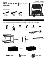
PARTS LIST
PARTS LIST
DESCRIPTION
DESCRIPTION
ORDER PART #
ORDER PART #
4
4
4
1
1
1
1
1
4
HW0295
HW0618
* NOTE: PARTS SHOWN ON PARTS LIST ARE NOT TO SCALE
A
C
D
E
F
G
H
I
J
K
L
M
N
ROCKER PLATE
FACTORY ASSEMBLY
Ø8.0 X 2.3 MM
SPRING WASHER
B1
B2
HW0004
8
Ø6.5 X 1.0 MM
WASHER
FOOT CAP
HW0442
BOLT COVER-1
8
1/4" X 20 MM
BOLT
HW0465
8
Fig. 4
Fig. 5
Step 1:
Do not attempt assembly if
any parts are missing or damaged.
Step 2:
Fig 1
Hand tighten only
Step 3:
Fig 2
Hand
tighten only
Step 4:
Do not over tighten. Over tightening may strip bolts.
Step 5:
Fig 3
If chair frame has been properly positioned on the rocker assembly, all arrows on the "U" bar
and rocker assembly will be pointing in the same direction.
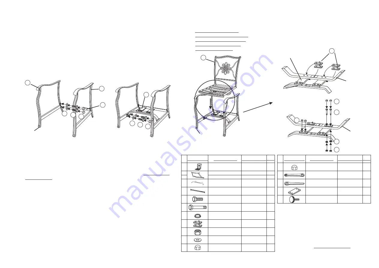
Step 6: Critical Step: The "U" metal plates must be installed in the proper location.
Fig 4
Fig 5 Hand tighten only.
CAUTION: Failure to place "U" metal plates under the rocker plates and above the "U" bar exactly as
shown in diagram will cause the bolt heads and nuts to damage the structure of the rocker plates and the
"U" bar. Damage due to over tightening of bolts or improper assembly could cause injury and may void
your warranty.
Step 7:
Do not over tighten.
Step 8:
.
,
.
,
.
.
.
,
,
.
Identify all parts packed in the carton against the parts list. Remove all protective materials. Place parts
on a non-abrasive surface to avoid scratching. If you are missing any parts or are unsure how to proceed
with the assembly, call our Customer Service Center at 1-800-416-3511.
Attach the leg support to the chair legs(B1 & B2) by using the 1/4"x20 mm bolts and washers as shown
in
. Guide these bolts through the holes in the leg support into pre-drilled holes in the chair legs.
.
Attach the support bar to the chair legs by using the 1/4"x20 mm bolts and washers as shown in
.
Guide these bolts through the holes in the support bar into the pre-drilled holes in the chair legs.
.
At this time make any adjustments to alignment of all parts. Tighten all bolts a few revolutions at a time,
alternating between bolts until tightened.
Set the chair frame on the rocker assembly with front of the seat facing you and the arrows on the "U"
bar pointing towards you as shown in
. This is very important for a safe, balanced rocking motion.
Adjust alignment of the holes of support bar and "U" bar Insert a "U" metal plate
as shown in
. Then guide the 5/16"x40 mm bolts through the holes in the "U" metal plate “U” bar,
rocker plate and bottom portion of the “U” metal plate. Add a Ø8.0 x 2.3 mm spring washer and a nut
to each bolt as shown in
.
Repeat the same procedure on the other side.
Tighten all nuts and bolts with the hex wrenches provided.
Remove arrow labels
from "U" bar and rocker assembly. Cover all bolts with bolt covers.
Your chair is ready for use. If you need any assistance, please call our Customer Service Center
at 1-800-416-3511.
Read this step and
carefully examine.
IMPORTANT NOTE: Damage to welds or frames resulting from over tightened bolts or improper
assembly is not covered under our warranty. Please read all instructions carefully before assembly. If you
have any questions regarding your assembly, call our Customer Service Center at 1-800-416-3511.
SEAT DESIGNS MAY
VARY BUT THE ASSEMBLY
IS THE SAME
ROCKER PLATE
"U" BAR
ROCKER
ASSEMBLY
"U" BAR
FC0030
FOOT CAP
FACTORY ASSEMBLY
"U" METAL PLATE
L
L
F
G
I
J


