background image


                                                                                                                                                                                                                       GRM00696G                                                                                                              


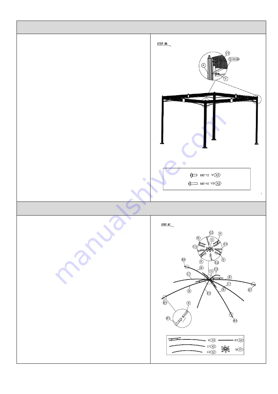
Step 6:


Connect the frame as shown and tighten 
the screws. 


Step 7:


Insert inclined tube 1 (B), inclined tube 3 
(C1), and inclined tube 4 (C2) into top kit 
(G) in the order of (B), (C1), (B), (C2), (B), 
(C1), (B), (C2). 


Insert the inclined tube 2 (B1) into the 
inclined tube 1 (B) as shown. 


Summary of Contents for GRM00696G

Page 1: ...r to build up in frames as this will cause corrosion and freeze damage in cold climates Wash all frames with a solution of mild soap and water Rinse with clean water and dry with a soft absorbent clot...

Page 2: ...ly exhibits normal wear yet functions essentially as new including chips scratches or stretching of materials and stitching 4 Tears punctures scratches or any damage caused by improper installation or...

Page 3: ...ns GRM00696G Aluminum and Steel Gazebo with Netting Questions problems or missing parts Before returning to the store call Customer Service 1 866 988 3300 8 a m 5 p m PST Monday Friday Retain this man...

Page 4: ...20 mm screw B1 4 Inclined tube 2 V2 8 1 M6 30 mm screw C1 2 Inclined tube 3 V3 24 2 M6 45 mm screw C2 2 Inclined tube 4 V4 8 1 Nut D1 2 Right long beam W 2 Inner allen wrench D2 2 Left long beam X 1...

Page 5: ...working surface to prevent product damage during assembly Need for assembly R 4 Leg base S 16 Rail beam washer T 4 Net U 1 Hook WARNING Please keep children out of the assembly area before assembly W...

Page 6: ...V Push the leg base cover Q to the bottom Step 2 On bottom side attach the right long beam D1 and the connector part M to the decorative plate F using M6 15mm screw V as shown On top side attach the R...

Page 7: ...GRM00696G 4 Attach the left long beam D2 to the connector part M using M6 15mm screw on the bottom side Step 3 Connect right short beam D3 and left short beam D4 according to step 2 Step 4...

Page 8: ...GRM00696G 5 Attach the beams D1 D2 to the post leg A using M6 15mm screw V and M6 45mm screw V3 as shown Step 5 Attach the beams D3 D4 to post leg A using M6 15mm screw V and M6 45mm screw V3 as shown...

Page 9: ...frame as shown and tighten the screws Step 7 Insert inclined tube 1 B inclined tube 3 C1 and inclined tube 4 C2 into top kit G in the order of B C1 B C2 B C1 B C2 Insert the inclined tube 2 B1 into t...

Page 10: ...1 to the U shape kit using M6 30mm screw V2 and nut V4 Attach the inclined tube 3 C1 and inclined tube 4 C2 to the middle kit using M6 30mm screw V2 and nut V4 Step 9 Attach the connector kit H and th...

Page 11: ...GRM00696G 8 Step 10 Put the large canopy O on the frame as shown Step 11 Put the small canopy N on top and...

Page 12: ...GRM00696G 9 tighten as shown Attach the decorative kit on top by screwing clockwise Step 12 Tighten the large canopy O as shown Step 13...

Page 13: ...M6 45mm screw V3 and rail beam washer S Attach the long rail beam E1 and short rail beam E2 to the decorative plate using M6 45mm screw V3 and rail beam washer S Step 14 Attach the net T to rail beam...

Reviews: