background image

11

In-service tests

Purpose

The purpose of in-service tests is to regularly monitor 
and record the performance of the thermostatic mixing 
valve. Deterioration in performance can indicate the 
need for service work on the valve and/ or the water 
supplies.

Procedure

1. 

Carry out the procedure 

2.

 (a) to (e) on page 72 

using the same measuring equipment, or equipment 
to the same specifications.

2. 

If  the  mixed  water  temperature  has  changed  signi-
ficantly  from  the  previous  test  results  (e.g.  >  1  K), 
record the change and before re-adjusting the mixed 
water temperature check:

a)  that any in-line or integral strainers are clean
b)  any  in-line  or  integral  check  valves  or  other 

anti-backsiphonage devices are in good working 
order

c)  any isolating valves are fully open

3. 

With an acceptable mixed water temperature, com-
plete the procedure 

2.

 (a) to (c) on page 10.

4. 

If at step 

2.

 (e) on page 10 the final mixed water tem-

perature is greater than the values in Table A and / or 
the maximum temperature exceeds the corresponding 
value from the previous test results by more than about 
2 K, the need for service work is indicated.


NOTE: In-service tests should be carried out with a 
frequency which identifies a need for service work 
before  an  unsafe  water  temperature  can  result.  In 
the absence of any other instruction or guidance, the 
procedure described in „Frequency of in-service tests“ 
may be used.

Frequency of in-service tests TMV2

The frequency of performing the in-service 

tests is 1 year maximum.

General 

In the absence of any other instruction or guidance on 
the means of determining the appropriate frequency of 
in-service testing, the following procedure may be used:

1. 

6 to 8 weeks after commissioning carry out the tests 
given in 

2.

 on page 10.

2. 

12 to 15 weeks after commissioning carry out the tests 
given in 

2.

 on page 10.

3. 

Depending on the results of 

1.

 and 

4.

 several possi-

bilities exist:

a)  If no significant changes (e.g. <


1 K) in mixed 

water temperatures are recorded between com-
missioning and 

1.

, or between commissioning and 

4.

 the next in-service test can be deferred to 24 

to 28 weeks after commissioning.

b)  If small changes (e.g. 1 to 2 K) in mixed water 

temperatures are recorded in only one of these pe-
riods, necessitating adjustment of the mixed water 
temperature, then the next in-service test can be 
deferred to 24 to 28 weeks after commissioning.

c)  If small changes (e.g. 1 to 2 K) in mixed water 

temperatures are recorded in both of these peri-
ods, necessitating adjustment of the mixed water 
temperature, then the next in-service test should be 
carried out at 18 to 21 weeks after commissioning.

d)  If significant changes (e.g. > 2 K) in mixed water 

temperatures  are  recorded  in  either  of  these 
periods, necessitating service work, then the next 
in-service test should be carried out at 18 to 21 
weeks after commissioning.

4. 

The general principle to be observed after the first 2 or 
3 in-service tests is that the intervals of future tests should 
be set to those which previous tests have shown can be 
achieved with no more than a small change in mixed 
water temperature.

Summary of Contents for Ecomax Bath / Shower

Page 1: ...EN Instructions for use assembly instructions Ecomax Bath Shower 14242000...

Page 2: ...n service tests 11 Thermostatic Adjustement Temperature Limitation 12 Callibrating Thermostat 12 13 Operating your Thermostat 14 AssemblingandOperatingtheDiverterFixingDevice 15 Cleaning 16 Spare Part...

Page 3: ...hildren well away from the work area Check for hidden pipes and cables in the wall before drilling holes The unit must be mounted on a finished waterproofed wall surface usually tiles If you are using...

Page 4: ...1 Ecomax Bath Shower 2 Mesh washers 3 Flow limiter when assembling the flow limiter the TMV2 certificate is invalid 4 Diverter fixing device Optional accessories 5 Escutcheons 6 S unions 7 Pillar uni...

Page 5: ...uildCert TMV scheme recommends the following set maximum mixed water outlet temperatures for use in all premises 44 C for bath fill but see notes below 41 C for showers 41 C for washbasins 38 C for bi...

Page 6: ...1 0 10 bar Unvented System pressure balanced 1 0 10 bar Pumped System 1 0 10 bar IMPORTANT If you install this mixer with a gravity fed system there must be a minimum head vertical distance from the...

Page 7: ...7 Unvented System pressure balanced Pumped System...

Page 8: ...8 Bath Shower Thermostat 180 mm Installation 36 39 mm Seal Shower Thermostat PTFE tape 150 mm HOT COLD 1 2 3 4...

Page 9: ...s 6 Fasten the thermostatic mixer onto the S unions using the union nuts Align the unit and tighten the nuts be careful not to damage the chrome finish The S unions allow inaccuracies to be compensate...

Page 10: ...o be different from those applied in the laboratory tests it is appropriate at commissioning to carry out some simple checks and tests on each mixing valve to provide a performance reference point for...

Page 11: ...performing the in service tests is 1 year maximum General In the absence of any other instruction or guidance on the means of determining the appropriate frequency of in service testing the following...

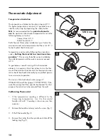
Page 12: ...er correct installation the outlet temperature of the water can never exceed 43 C To guarantee a smooth running of the thermostatic element it is necessary from time to time to turn the ther mostat fr...

Page 13: ...spindle until the required maximum tem perature is reached 40 C You will need to use a thermometer fig 4 6 Replace the locking ring back onto the spindle as shown Refit the circlip fig 5 7 Replace th...

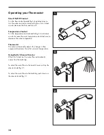
Page 14: ...k wise to increase the water temperature and clockwise to decrease the water temperature Thermostat The valve automatically adjusts for changes in flow supply and maintains the outlet set water temper...

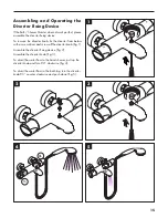
Page 15: ...the diverter from below with a screw driver and screw off the diverter knob fig 1 Assemble the diverter fixing device fig 2 Assemble the diverter knob fig 3 To divert the water flow to the hand shower...

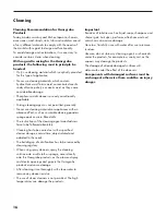
Page 16: ...e cleaning agent manufacturers have to be followed absolutely Cleaning has to be carried out with a specified cleaner dosage contact time object related and adapted to the needs The building up of cal...

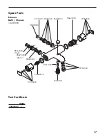
Page 17: ...e Parts Ecomax Bath Shower 14242000 96633000 92929000 97469000 97335000 97163000 96488000 97164000 97210000 96922000 97211000 96644000 97510000 98163000 15x2 98421000 28x1 5 Test Certificate WRAS 1424...

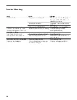
Page 18: ...er pipe or vice versa when mixer is closed Backflow preventers dirty or leaking Clean backflow preventers exchange if necessary Spout temperature does not correspond with temperature set Thermostat ha...

Page 19: ...grohe will remedy this defect free of charge You will find the conditions and details of this guarantee at www hansgrohe int com guarantee Please contact your contracting party to claim your rights un...

Page 20: ...0 Hansgrohe Units D1 D2 Sandown Park Park Trading Estate Royal Mills Esher Surrey KT10 8BL Technical Hotline 01372465655 E Mail technical hansgrohe co uk Internet www hansgrohe co uk 07 2018 9 05577 0...

Reviews: