27
2020/09
5.8
Status indicators/diagnostic messages
The gateway transmits the following diagnostics: the status of the BL20 station, the communication
via the internal module bus, the communication to CANopen and the status of the gateway.
Diagnostics messages are indicated in two different ways:
via the LEDs
via the software of the respective higher (for example PLC)
5.8.1
Diagnostic messages via LEDs
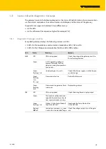
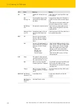
Every BL20 gateway displays the following statuses via LEDs:
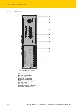
2 LEDs for the module bus communication (module bus LEDs): GW and IOs
2 LEDs for the CANopen communication (field bus LEDs): ERR and Bus
LED
Status
Meaning
Remedy
GW
Off
CPU not supplied.
Check the wiring at the gateway or at the
Bus refreshing module.
Green
5 V DC operating voltage is
present; firmware is active;
gateway is ready for operation
and transfer
-
Green
flashing, 1 Hz
Undervoltage at U
sys
or U
L
Check if the Power supply is within the per
-
missible range.
Green
flashing,
1 Hz
IOs: red
Firmware not active
Reload the firmware
Green
flashing,
4 Hz
Firmware active, gateway hard
-
ware error.
Replace the gateway.
IOs
Off
CPU not supplied.
Check the wiring Power supply output.
Green
The modules configured corre
-
spond to the modules in the sta
-
tion, communication running.
-
Green
flashing, 1 Hz
Station is in the Force Mode of
the I/O-ASSISTANT
Deactivate the Force Mode of the
I/O-ASSISTANT
Red and
GW
off
Controller is not ready, U
sys
level
is not within the required range.
Check the voltage supply Usys at the gate
-
way.
Summary of Contents for BL20-ECO
Page 1: ...Your Global Automation Partner BL20 E GW CO ECO Gateway for CANopen Instructions for Use...
Page 2: ...2 Hans Turck GmbH Co KG T 49 208 4952 0 F 49 208 4952 264 more turck com www turck com...
Page 6: ...Hans Turck GmbH Co KG T 49 208 4952 0 F 49 208 4952 264 more turck com www turck com 4...

