-
9
-
5
Gas test
when the switch is in ‘Gas test’, the solenoid valve is on, CO
2
gas flow can be checked if it is of suitable amount
6
Wire feeder
Connect the wire feeder control cable.
7
-
Welding machine output negative
8
+
Welding machine output anode
9
Inductance
regulation
when in MAG or spot welding condition, will change welding
stability,penetration and splash
10
Crater arc voltage
MAG: adjust the crater arc voltage when in “crater arc on”
MMA: adjust the pushing current,Can change the arc stiffness,
reducing welding spatter
Spot welding: adjust spot welding time
11
Crater arc current
MAG: adjust the crater arc current when in “crater arc on”
MMA: adjust the welding current
Spot welding: adjust spot welding interval time
12
Wire feeding(8A) When the control circuit of wire feeder is in a short circuit, the
fuse will break to protect the transformer.
13
Power supply box Used to connect the welder into 380V power.
14
Air break switch
Aim to protect the welder from overloading or defect. Under
normal condition, the switch is lifted up and stays on
15
Power
(
2A
)
When the control circuit of welding machine is in a short
circuit, the fuse will break to protect the transformer.
16
Heating fuse(8A) When there is a short circuit in the heating pressure reducing
flow meter, the fuse will break to protect the transformer.
17
Heating
power
output plug
To provide 36V heating power for heating pressure reducing
flow meter
18
Cooling fan
To cool the internal parts.
19
Grounding bolt
Ground this bolt securely for safety.
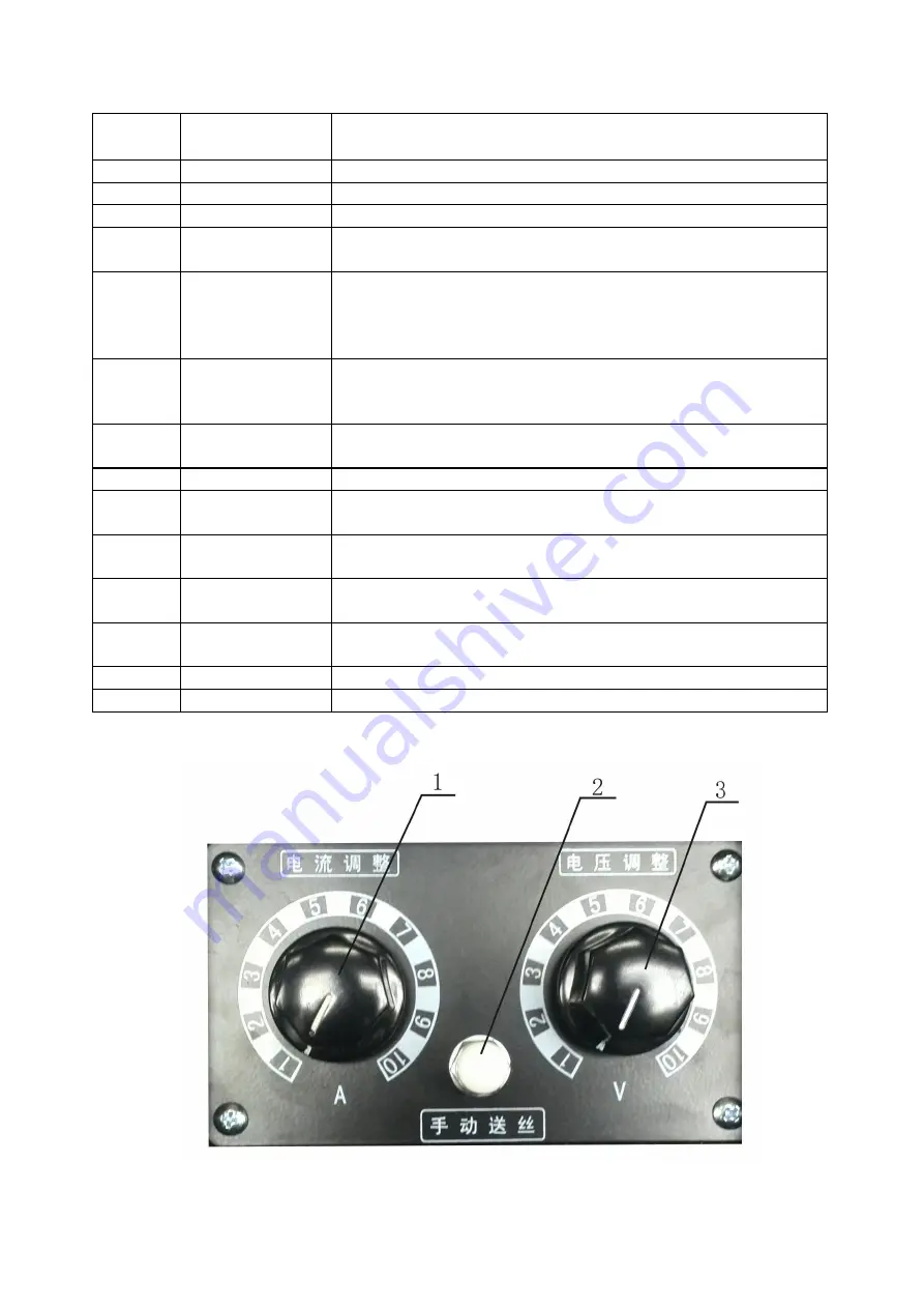
5.2 Wire feeder panel
Figure 3. Control panel illustration of wire feeder


