Spider
EN
Feeding computer
-
Voercomputer
-
Fütterungscomputer
-
Logiciel d
’
alimentation
Index
13
-
46
Hanskamp AgroTech B.V. (The Netherlands)
www.hanskamp.nl/en
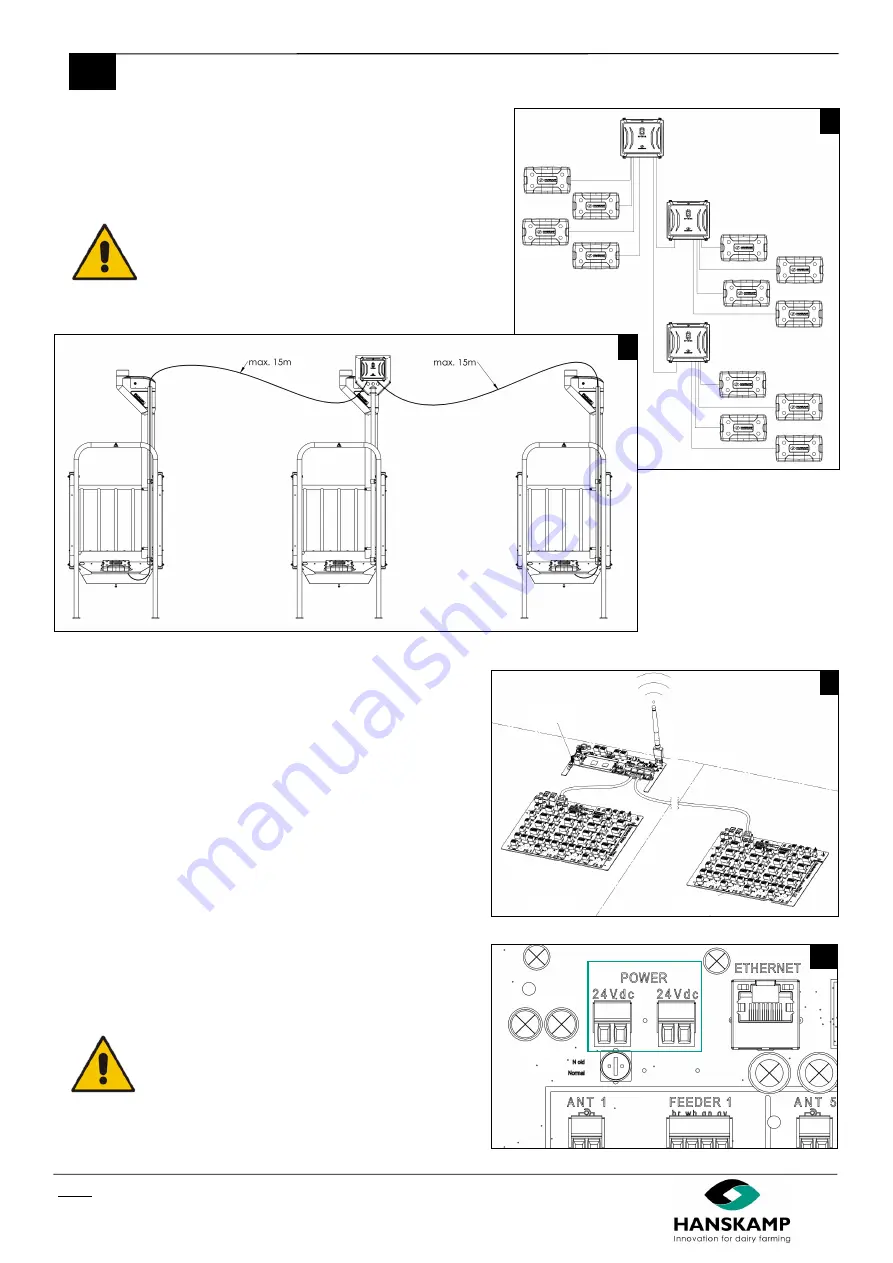
The SpiderPCB can be freely configured, allowing control of up to 16
feeding stations with 1 feed type. If this is not enough, the SpiderServer
can be expanded with a SpiderClient, doubling the number of inputs
and outputs. Connect the units with a shielded data cable (art. no. 005
-
109
-
000 SF/UTP CAT5E).
Caution! The feeding stations must not be more than 10
meters apart, as the Antenna cable is 15 meters long.
If they are further apart, you will need to use an extra
SpiderClient.
5.
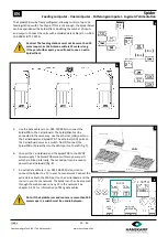
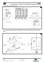
Use the data cable (art. no. 005
-
107
-
000) to connect the
SpiderPCB to the CarrierBoard. The SpiderClient can be
connected in the same way. Use the ethernet (LAN) ports on
the CarrierBoard and SpiderPCB. The ethernet (LAN) ports on
the CarrierBoard serve as a switch. Do NOT connect the
SpiderPCB or SpiderClient to the WAN port on the left (fig. 7).
6.
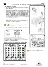
Connect the CarrierBoard and the SpiderPCB to the 24VDC
power supply. The SpiderPCB comes with two power ports
which are linked internally. The second port can be used to
power the CarrierBoard (fig. 8).
7.
An extra data cable (art. no. 005
-
109
-
000) is required to
connect the Spider to a PC in your home network. Connect the
extra data cable to the WAN port on the CarrierBoard and the
router in your home network. The Spider can then be accessed
through the web browser on any PC in the network. See
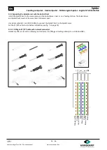
chapter 3.2.3.1 for information on fitting data cables.
Note: If the SpiderServer and router are more than 100
meters apart, a switch must be used in between.
5
6
7
8
SpiderServer
SpiderClient
SpiderClient
LAN
CarrierBoard
SpiderPCB
SpiderPCB
SpiderServer
SpiderClient

