Spider
EN
Feeding computer
-
Voercomputer
-
Fütterungscomputer
-
Logiciel d
’
alimentation
Index
19
-
46
Hanskamp AgroTech B.V. (The Netherlands)
www.hanskamp.nl/en
3.3 Installation in the milking parlour
As Spider has 16 Antenna inputs and 16 feed outputs, it can also be used for individual feeding in the milking parlour. Every
position can be seen as a feeding station. Please refer to chapter 3.2.1 for instructions on how to connect.
3.3.1 Connecting the limit switch
A limit switch can be installed to prevent animals from being recognised and stopping before the last stall. The limit switch
deactivates the Antennas during the switch. This prevents feeding until all the cows are in the correct position.
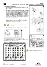
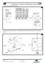
The below example shows the correct set up for a 2x8 milking parlour.
Detection port
1
works for feeder
1
-
4
2
works for feeder
5
-
8
3
works for feeder
9
-
12
4
works for feeder
13
-
16
This can be continued as in the example. In this instance, one switch is used for feeders 1
-
8 and one for feeders 9
-
16.
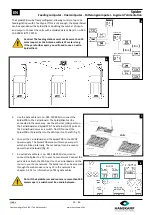
Detection 1 and 2 are connected in this example
Side A
Side B
Read yellow as green in direction SpiderPCB
The Antennas are inoperative when the
switch is
operated
. Connect the brown
and green wires. (NO)
The Antennas are inoperative when the
switch is
not operated
. Connect the
brown and yellow wires. (NC)
Milking parlour 2x8
Side A
Side B
NO

