Spider
EN
Feeding computer
-
Voercomputer
-
Fütterungscomputer
-
Logiciel d
’
alimentation
Index
27
-
46
Hanskamp AgroTech B.V. (The Netherlands)
www.hanskamp.nl/en
5.
Adjusting the FloorAntenna
Note! Ensure that the RFID settings are properly configured before setting up the FloorAntenna (frequency,
transponder type, etc.).
Caution! Ensure that all FloorAntennas are connected and fixed in position. The mounting hardware must not
be in contact with surrounding steel (e.g. concrete reinforcement).
Position the Spider unit in such a way that the LED lighting on the unit is visible from the point of adjustment.
1.
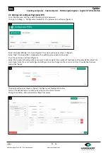
Start de RFID LED
’
s.
‘
Settings
’
-
>
‘
Maintenance
’
-
>
log in as admin.
2.
‘
Settings
’
-
>
‘
Configuration SpiderPCB
’
-
>
choose the applicable SpiderPCB
-
>
‘
Parameters
’
-
>
‘
RFID: LEDS on when detect
(0=off/1=on)
’.
Set to
‘1’.
This causes the LED associated with the connected Antenna(s) to light up red and flash green
when transponder is recognized.
3.
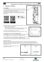
Loosen the adjusting screw in the EWA until the green LED switches off.
4.
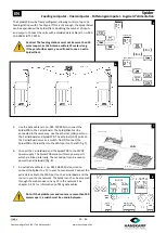
Hold the transponder facing outwards approx. 20 cm above the ground,
just to the right of the centre within the boundaries of the Antenna (see
below image). Use for example a piece of PVC tube to hold it in place.
5.
Tighten the adjusting screw in the EWA until the LED for the relevant
Antenna flashes green. If the adjusting screw is fully tightened but the transponder is still not being identified, move the
transponder further in. If it is recognised, the EWA is correctly adjusted.
6.
Test whether the transponder works everywhere within the Antenna and that there is no crosstalk with other
Antennas. If there is crosstalk between Antennas, loosen the adjusting screw until the desired range is achieved.
7.
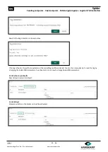
Close the DEBUG mode. See step 1 and change
‘
RFID: LEDS on when detect
(0=off/1=on)
’
back to
‘0’
and click
‘
Save
’.
TIP: Use our FieldTester (art. no. 005
-
130
-
000) to adjust and check the field.
Adjusting screw

