DPO6000, MPO6000 Series Digital Fluorescent Oscilloscope Product Manual V1.3
10
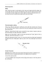
Probe inspection
Safety
When using the probe, to avoid electric shock, keep your fingers behind the safety ring
on the probe body. Do not touch the metal part on the top of the probe when the probe
is connected to a high voltage power supply. Before making any measurements, con-
nect the probe to the oscilloscope and ground the ground terminal.
Probe attenuation setting
Probes have different attenuation coefficients, which affect the vertical scale of the sig-
nal. The "Probe Check" function verifies that the probe attenuation options match the
probe attenuation.
Press the "Vertical Menu" button (such as the [CH1] menu button) to select a probe op-
tion that matches the probe attenuation coefficient.
Make sure the "Attenuation" switch on the probe matches the "Probe" option in the os-
cilloscope, and set the switches to X1, X10.
When the Attenuation switch is set to X1, the probe limits the oscilloscope's bandwidth
to 6MHz. When the "Attenuation" switch is set to X10, the oscilloscope has full band-
width.
Connect the probe
DPO6000 series oscilloscopes are equipped with passive probes as standard, and
MPO6000 series are equipped with passive and digital probes as standard.
Connect the passive probe:
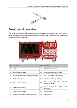
1. Connect the BNC end of the probe to the analog channel input on the front panel of
the oscilloscope.


