DPO6000, MPO6000 Series Digital Fluorescent Oscilloscope Product Manual V1.3
30
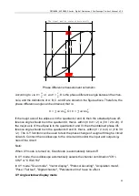
A
The signal must be centered horizontally
B
C
D
Ⅰ
Ⅱ
Ⅲ
Ⅳ
Phase difference measurement schematic
According to
sin 𝜃 =
𝐴
𝐵
or
sin 𝜃 =
𝐶
𝐷
, θ is the phase difference angle between the chan-
nels, and the definitions of A, B, C, and D are shown in the figure above. Therefore, the
phase difference angle can be obtained, that is:
θ = ± arcsin
𝐴
𝐵
Or
θ = ± arcsin
𝐶
𝐷
If the major axis of the ellipse is in the quadrants I and III, then the obtained phase dif-
ference angle should be in the quadrant III, that is, within (0 to π / 2) or (3π / 2 to 2π). If
the major axis of the ellipse is in the quadrants II and IV, then the obtained phase dif-
ference angle should be in the quadrants II and III, that is, within (π / 2 to π) or (π to 3π
/ 2). The X-Y function can be used to test the phase change of a signal through a circuit
network. Connect the oscilloscope to the circuit and monitor the input and output sig-
nals of the circuit.
Note:
When XY mode is turned on, Scan Mode is automatically turned off.
In XY mode, the oscilloscope automatically selects the channel combination "CH1-
CH2" or "CH3-CH4".
In XY mode: "Scan mode", "Vector display", "Protocol decoding", "Acquisition mode",
"Pass / Fail test", "Digital channel", "Persistence time" have no effect.
XY single window display mode

