


DPO6000, MPO6000 Series Digital Fluorescent Oscilloscope Product Manual V1.3
62
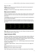
[Mode]
Select the acquisition mode (auto, normal) and press V0 to confirm.
[Holdoff]
Set the holdoff time.
[Decode]
Switch decoding function
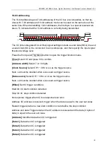
[Label position]
The position where the decoded data is drawn on the screen (only
available when the decode function is turned on).
[Table]
Data recording mode
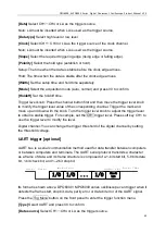
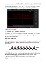
Trigger level knob: The analog channel can modify the trigger level value. Trigger the
mark and move up and down with the knob.
Digital channel: You can change the trigger threshold of the digital channel by setting
the threshold voltage.
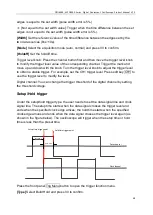
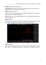
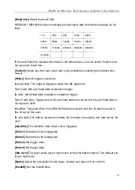
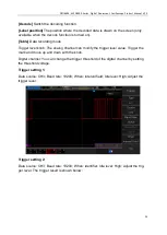
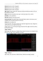
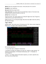
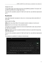
Trigger settings:
Address width: 7 bits; clock source: CH4; data source: CH3; When: start bit. Adjust the
trigger level. The trigger result is displayed as follows:
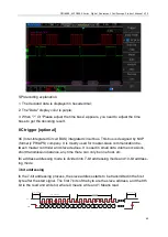
IIC decoding explanation:
1. The decoded data is displayed in hexadecimal;
2. "Address" and "Data" are displayed in purple; "W" indicates a write operation, "R"
indicates a read operation, "D" indicates decoded data, and "~ A" indicates no
acknowledge bit;
3. When “?” Or “Please adjust the time base” appears, you need to adjust the time
base to get the decoding result.


