background image

0

8060

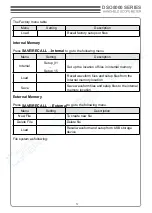
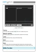
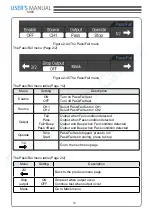
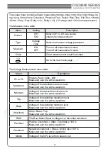
Load

Recall mask setting file from internal memory


Back to the previous menu page

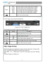
The Mask setting menu (Page 2/2) When the save as external memory

Menu

Setting

Description

Save

Go to save menu (same as REF save menu)

Load

Recall mask setting file from external memory

Waveform Recorder

Waveform recorder records input waveforms from CH1 and CH2, with a maximum record 

length of 1000 frames.

Press 

Utility→Record

 Setting to go to the following 

Waveform recorder

: Record the waveforms with specified interval.

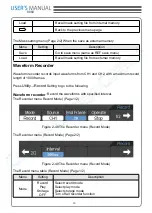
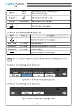
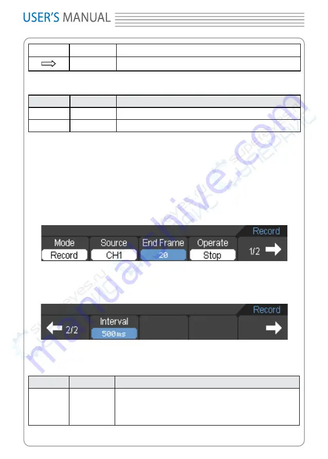
The Recorder menu Record Mode) (Page 1/2)


Figure 2-48 The Recorder menu (Record Mode)

The Recorder menu (Record Mode) (Page 2/2)


Figure 2-49 The Recorder menu (Record Mode)

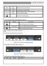
The Record menu table (Record Mode) (Page 1/2)

Menu

Setting

Description

Mode

Record

Play 

Storage

OFF

Select record mode

Select play mode

Select storage mode

Turn off all recorder function

Summary of Contents for DSO8000 Series

Page 1: ...www hantek com DSO8000 SERIES HANDHELD SCOPEMETER 8060 USER SMANUAL...

Page 2: ...DSO8000 SERIES USER S MANUAL 8060...

Page 3: ...tically 15 Using the Scope Meter 16 CHAPTER 2 Operating Scope 19 Set Vertical System 20 Set Horizontal System 36 Set Trigger System 40 Save Recall Waveforms and Setups 48 Utility Function 52 Signal Me...

Page 4: ...nstrument or other property might occur Symbols on the Product These symbols may appear on the product Hazardous Refer to Protective Grounding Test Voltage Instructions Earth Terminal Terminal Groundi...

Page 5: ...for your measurement Avoid Circuit or Wire Exposure Do not touch exposed connections and components when power is on Do Not Operate With Suspected Failures If suspected damage occurs with the device h...

Page 6: ...c measurements Automatic cursor tracking measurements Waveform recorder record and replay dynamic waveforms User selectable fast offset calibration Built in FFT function Frequency Counter Pass Fail Fu...

Page 7: ...APTER 1 Getting Start This chapter covers the following topics General Check Functional Check The User Interface Input Connections To compensate probes To display a signal automatically Using the Scop...

Page 8: ...our distributor at your local area or the overseas sales dept Check the instrument In case there is any mechanical damage or defect or the instrument does not operate properly or fails performance te...

Page 9: ...8060 Figure 1 1 Scope Meter Front Panel v...

Page 10: ...play 2 F1 F5 Sets or switch options for the menu 3 Arrow Keys 4 HORI Shows Horizontal menu 5 TRIG Shows Trigger menu 6 LEVEL Adjust the trigger level 7 RUN STOP key for running or stopping the operati...

Page 11: ...th or REF menu 15 DMM Buttons The DMM control buttons 16 DMM SCOPE Switch DMM Scope or RPM function 17 MENU ON OFF Turn on off the menu 18 SAVE RECALL Shows SAVE or RECALL menu 19 MEAS Shows Measureme...

Page 12: ...igger source 7 Shows the trigger level 8 Shows the power 9 The center of current waveform window 10 CH1 waveform 11 The trigger level symbol 12 The grid 13 CH2 waveform 14 Shows the time base 15 Shows...

Page 13: ...he power adapter is supplied for AC power supply and battery recharging 2 Multi meter input jacks including four circular banana jacks The four circular jacks are used for voltage resistance mA range...

Page 14: ...s Align the slot in the probe connector with the key on the CH1 BNC connector Push to connect and twist to the right to lock the probe in place Attach the probe tip and ground lead to the OUTPUT port...

Page 15: ...probe attenuation to 10X press CH1 Probe 10X Set the switch to X10 on the probe and connect it to CH1 of the scope meter When usiing the probe hook tip insert the tip onto the probe firmly to ensure...

Page 16: ...e meter to best display the input signal Using Auto requires signals with a frequency greater than or equal to 50 Hz and a duty cycle greater than 1 Press the AUTO button the scope meter turns on and...

Page 17: ...power adapter The scope meter can still work with built in Li ion battery even without AC power supply Turn the scope meter on by pressing down the power on off key The instrument then performs Self...

Page 18: ...ss it to change function setting Set up the vertical system 1 Change the vertical setup and notice that each change affects the status bar differently Change the vertical sensitivity with or button an...

Page 19: ...gger point position Set up the trigger system 1 Change the trigger Level The or button changes the trigger level The trigger level value is displayed at the top right of the screen and a line is displ...

Page 20: ...determine the system setup from the status bar of a Scope Meter This chapter will detail the scope meter function of the test tool Set Vertical System Set Horizontal System Set Trigger System Save and...

Page 21: ...s in the menu are shown in the table below To make vertical CH1 and CH2 settings do the following 1 Press the CH1 or CH2 button and then the function menu appears at the bottom of the screen 2 Select...

Page 22: ...signal Probe 1X 10X 100X 1000X Select one according to the probe attenuation factor to ensure correct vertical scale reading Reset Set the vertical display position back to middle window 1 2 Go to the...

Page 23: ...be displayed in the status bar on the bottom of the screen Figure 2 2 Channel Volt Div Press CH1 Volt Div Coarse Fine to Set Volt Div range 2 Set Channel Coupling With CH1 taken for example input a si...

Page 24: ...23 DSO8000 SERIES Figure 2 3 Waveform Display Press CH1 Coupling DC to set DC coupling It will pass both AC and DC components of the input signal The waveform is displayed as Figure 2 4...

Page 25: ...24 8060 Figure 2 4 Waveform Display Press CH1 Coupling GND to set GND coupling it disconnects the input signal The screen displays as Figure 2 5...

Page 26: ...ion scale The attenuation factor changes the vertical scaling of the scope meter so that the measurement results reflect the actual voltage levels at the probe tip To change or check the probe attenua...

Page 27: ...26 8060 4 Invert a waveform The displayed waveform reverses 180 degrees relatively to the ground potential Press CH1 or CH2 F5 F3 to turn on off the Invert Figure 2 7 Turn Invert off...

Page 28: ...h CH1 taken for example input a signal containing high frequency component Press CH1 F5 F4 OFF to set up bandwidth limit to OFF status The scope meter is set to full bandwidth and passing the high fre...

Page 29: ...28 8060 Figure 2 9 Turn BW limit Off Press CH1 F5 F4 ON to set up bandwidth limit to ON status It will reject the frequency component higher than 20MHz The waveform is displayed as Figure 2 10...

Page 30: ...thematic functions include add subtract multiply division and FFT for CH1 and CH2 The mathematic result can be measured by the grid and the cursor The mathematic window is displayed as figure 2 11 The...

Page 31: ...B 1 2 Go to the next menu page 2 2 Back to the previous menu page Volt Div Coarse Fine Set Voltage range coarsely Set Voltage range finely Invert ON OFF Invert the MATH waveform Waveform display norm...

Page 32: ...nverts a time domain signal into its frequency components mathematically FFT waveforms are useful in the following applications Measure harmonic content and distortion in systems Characterize noise in...

Page 33: ...rm in split screen 2 2 Back to the previous menu page Note 1 Signals that have a DC component or offset can cause incorrect FFT waveform component magnitude values To minimize the DC component choose...

Page 34: ...amming Better frequency poorer magnitude accuracy than Rectangular Hamming has slightly better frequency resolution than Hanning Sine periodic and narrow band random noise Transients or bursts where t...

Page 35: ...the following menu REF menu when using internal memory Figure 2 16 The Internal menu REF menu table when using internal memory Menu Setting Description Enable ON OFF Turn on REF Turn off REF Source C...

Page 36: ...CH1 CH2 Select CH1 as REF channel Select CH2 as REF channel Location Internal External Select inner memory location Select outer memory location 1 2 Go to the next menu page External Press M R REF Ext...

Page 37: ...r MATH 3 Press F4 to save REF 4 Press F5 to load an internal REF file 5 Press F1 button to turn on REF Note The Reference function is not available in X Y mode Set Horizontal System The horizontal sys...

Page 38: ...w CH1 value at X axis CH2 value at Y axis In Roll Mode the waveform display updates from right to left Reset Pressing this button clears trigger offset and moves the trigger point to the horizontal ce...

Page 39: ...position in the memory 4 The trigger position in the current waveform window 5 The horizontal time base main time base ALT Mag The ALT Mag is a magnified portion of the waveform window Use ALT Mag to...

Page 40: ...r half displays an expanded portion of the main waveform window This expanded portion of the main window is called the ALT Mag window Two blocks shadow the upper half The un shadowed portion is expand...

Page 41: ...to acquire data and display a waveform When a trigger is set up properly it can convert unstable displays or blank screens into meaningful waveforms When the scope meter starts to acquire a waveform i...

Page 42: ...ther the oscilloscope finds the trigger point on the rising or the falling edge of a signal Select Edge trigger mode to trigger on rising edge falling edge Press TRIG F1 Edge button to show the edge t...

Page 43: ...The Pulse Trigger Menu The Pulse Trigger menu Page 2 2 Figure 2 28 The Pulse Trigger Menu The Pulse Trigger Table Page 1 2 Menu Setting Description Source CH1 CH2 Define CH1 or CH2 as trigger signal...

Page 44: ...re the waveform ALT Alternative Trigger Setting When alternative trigger is on the trigger sources come from two vertical channels This mode can be used to observe two non related signals You can choo...

Page 45: ...12 11 10 9 8 5 7 6 4 3 14 Figure 2 29 ALT Mode Screen Description 1 The trigger type of CH1 2 The horizontal trigger position of CH1 3 The trigger level value of CH1 4 The trigger type of CH2 5 The tr...

Page 46: ...e previous menu page HF Reject ON OFF Reject high frequency signals or not 50 Set the trigger level to the center of the signal 2 2 Back to the previous menu page The ALT Trigger menu Type Pulse Page...

Page 47: ...gure 2 33 The ALT Trigger menu The Alternative menu table Trigger Type Pulse Page 2 2 Menu Setting Description 2 2 Back to the previous menu page Setting Value Set the width of the pulse HF Reject ON...

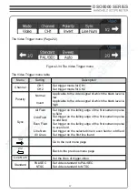
Page 48: ...Sync All Field Odd Field Even Field Line Num All Lines Set trigger on the falling edge of the first serration pulse to field Set trigger on the falling edge of the first serration pulse to odd field...

Page 49: ...n the un stability of waveforms can be detected by Auto Trigger such as the output of Power supply NOTE When horizontal control is set more than 50 ms div Auto mode allows the oscilloscope to capture...

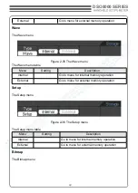
Page 50: ...Setting Description Internal Go to menu for internal memory operation External Go to menu for external memory operation Setup The Setup menu Figure 2 36 The Setup menu The Setup menu table Menu Setti...

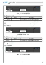
Page 51: ...u Setting Description External Go to menu for external memory operation CSV The CSV menu Figure 2 38 The CSV menu The CSV menu table Menu Setting Description External Go to menu for external memory op...

Page 52: ...Load Recall waveform files and setup files from the internal memory location Save Save waveform files and setup files to the internal memory location External Memory Press SAVE RECALL External to go t...

Page 53: ...fy the memory location to save recall the waveforms and setups Load Recall saved waveforms setups and default settings Save Save waveforms and setups Note 1 Select save stores not only the waveforms b...

Page 54: ...ttings in the Utility system The series without LAN The Utility menu Page 1 4 The Utility menu Page 2 4 The Utility menu Page 3 4 The Utility menu Page 4 4 Figure 2 41 The Utility menu without LAN The...

Page 55: ...with LAN The Utility menu table Page 1 4 and Page 1 5 Menu Setting Description F C R OFF Turn off Frequency Counter or RPM Frequency Turn on Frequency Counter Turn on Counter RPM Turn on RPM DMM ON OF...

Page 56: ...e Record Go to Record menu page Language Select languages More languages may be added in later firmware versions 2 4 Go to the next menu page 2 5 Go to the next menu page The Utility menu table Page 3...

Page 57: ...e first previou menu page 4 5 Go to the next menu page The Utility menu table Page 5 5 Menu Setting Description 5 5 Back to the previous menu page IO Set Go to the IO Set menu Page 5 5 Go the the firs...

Page 58: ...must have been working or warm up at least 30 minutes before running calibration to get best accuracy The scope meter will calibrate parameter of vertical system CH1 CH2 Pass Fail The Pass Fail funct...

Page 59: ...Pass Fail Beep Pass Beep Output when Fail condition detected Output when Pass condition detected Output and Beep when Fail condition detected Output and Beep when Pass condition detected Operate Stop...

Page 60: ...Setting Description Vertical Set vertical clearance to the waveform Horizontal Set horizontal clearance to the waveform Create Create a test mask according to the above clearance Location Internal Ex...

Page 61: ...forms from CH1 and CH2 with a maximum record length of 1000 frames Press Utility Record Setting to go to the following Waveform recorder Record the waveforms with specified interval The Recorder menu...

Page 62: ...nu table Record Mode Page 2 2 Menu Setting Description 2 2 Back to the previous menu page Interval 10 0ms 20s Set time interval between record frames Back to the Utility menu page Play Play back the r...

Page 63: ...enu Setting Description 2 2 Back to the previous menu page Start Frame 1 1000 Set start frame Cur Frame 1 1000 Select current frame to be played End Frame 1 1000 Set End frame Back to the previous men...

Page 64: ...emory location Load Recall recorded waveform from internal memory location Back to the Utility menu page The Record menu when the save as external memory Storage Mode Page 2 2 Menu Setting Description...

Page 65: ...ure menu The measure menu Page 2 5 Figure 2 55 The Measure menu The measure menu Page 3 5 Figure 2 56 The Measure menu The measure menu Page 4 5 Figure 2 57 The Measure menu The measure menu Page 5 5...

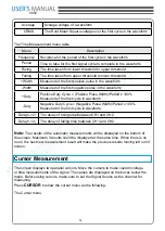
Page 66: ...The Voltage Measurement menu table Menu Description Pk to Pk Peak to Peak Max Min Measured over the entire waveform Maximum Voltage of the absolute maximum level Measured over the entire waveform Mini...

Page 67: ...rst cycle in waveform Duty Negative Duty Cycle Negative Pulse Width Period x 100 Measured of the first cycle in waveform Delay1 2 The delay of rising time between CH1 and CH2 Delay1 2 The delay of fal...

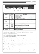
Page 68: ...the increments between the two cursors To do cursor measurements please do as the following steps 1 Turn on the cursor measurement Cursor Mode Manual Track Auto 2 Select channel Source for measuremen...

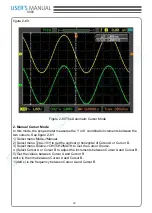
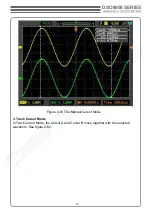
Page 69: ...ct menu Mode Manual 2 Select menu Type X Y to get the vertical or horizontal of Cursor A or Cursor B 3 Select menu Source CH1 CH2 MATH to Get the Cursor Source 4 Select Cursor A or Cursor B to adjust...

Page 70: ...69 DSO8000 SERIES Figure 2 61 The Manual Cursor Mode 3 Track Cursor Mode In Track Cursor Mode the Cursor A and Cursor B move together with the selected waveform See figure 2 62...

Page 71: ...lect Cursor A or Cursor B Move the Select Cursors to adjust the increments between the Cursors 4 Get the values between Cursor A and Cursor B delt x is the time between Cursor A and Cursor B 1 delt x...

Page 72: ...tility menu page Press the button F2 in the IO Set menu LAN then a small window pops up You can select the Arrow keys to move the cursor position in which you want to modify parameter then press the E...

Page 73: ...easure the frequency and Vpp you can do these steps as followings 1 Press the key MEAS Select Source CH1 and select Type Voltage then press the key F5 and then press the key F2 to make a Pk to Pk test...

Page 74: ...attenuation to x10 Set the switch to x10 on the probes 2 Connect the CH1 probe to the input of the circuit and connect the CH2 probe to the output of the circuit 3 Click the key AUTO on the panel 4 A...

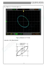
Page 75: ...75 DSO8000 SERIES See Signal in X Y Format in figure 3 2 Figure 3 2 Signal in X Y Format Instruction of the Ellipse Method...

Page 76: ...The FFT Cursor Measurements FFT measurement includes Amplitude measurement Vrms or dBVrms and the Frequency measurement Hz Do these steps as followings 1 Press the key CURSOR to show Cursor menu 2 Sel...

Page 77: ...utput is built in as a standard feature and is optically isolated Do the steps as followings 1 Press the key Utility to enter the Utility menu 2 Press the key F5 in the panel to enter the page 2 4 3 S...

Page 78: ...noise Select the Acquire Mode in Acquire menu If there is noise within the signal and the waveform looks too wide in this case choose average acquisition In this mode the waveform will be thin and ea...

Page 79: ...79 DSO8000 SERIES See signal after reducing random noise in figure 3 7 Figure 3 6 Signal with random noise...

Page 80: ...ld work on a rising edge Do these steps as followings 1 Set the probe and the channel attenuations to 10X 2 Press the key TRIG to show the Trigger menu 3 Select Mode Edge Set Source to CH1 and Slope t...

Page 81: ...ntroduction gives guides to show how to use the menus and perform basic measurements Connecting the Meter Use the 4 mm safety banana jack inputs for the Meter functions 10A mA COM V C Multimeter Opera...

Page 82: ...automatically measuring range control Operating the Multimeter If you are in the scope mode window press OSC DMM key the scope meter will switch to the multimeter mode window Then the screen will disp...

Page 83: ...he diode key and a diode symbol appears at the top of the screen 2 Insert the black lead into the COM banana jack input and the red lead into the V C banana jack input 3 Connect the red and black lead...

Page 84: ...he top of the screen 2 Insert the black lead into the COM banana jack input and the red lead into the V C banana jack input 3 Connect the red and black leads to the tested points If the resistance val...

Page 85: ...C key and a capacitor symbol appears on the top of the screen 2 Insert the black lead into the COM banana jack input and the red lead into the V C banana jack input 3 Connect the red and black leads t...

Page 86: ...key and DC appears at the top of the screen 2 Insert the black lead into the COM banana jack input and the red lead into the V C banana jack input 3 Connect the red and black leads to the measured po...

Page 87: ...ars on the screen 2 Press the F1 key and AC appears on the screen 3 Insert the black lead into the COM banana jack input and the red lead into the V C banana jack input 4 Connect the red and black lea...

Page 88: ...on the main reading screen is mA Press F2 to switch the measurement between mA and 10A 600mA is acquiescently 2 Insert the black lead into the COM banana jack input and the red lead into the mA banan...

Page 89: ...2 Press F2 key to switch to 10A measurement the unit on the main reading screen is A 3 Insert the black lead into the COM banana jack input and the red lead into the 10A banana jack input 4 Connect t...

Page 90: ...n the bottom of the screen press F2 to switch the measurement between mA and 10A 600mA is acquiescently 2 Press the F1 key once and AC will display on the bottom of the screen 3 Insert the black lead...

Page 91: ...surement the unit on the main reading screen is A 3 Press the F1 key once and AC will display on the bottom of the screen 4 Insert the black lead into the COM banana jack input and the red lead into t...

Page 92: ...t is required to acquire a reference value 1 Press the key 2 Insert the black lead into the COM banana jack input and the red lead into the V C banana jack input 3 Connect the red and black test leads...

Page 93: ...ange mode and then Manual is displayed on the top of the screen 2 Under the manual range mode the measuring range is increased by a stage when pressing F4 key each time and when reaching the highest s...

Page 94: ...94 8060 Figure 4 13 The Manual Range Mode Then the screen will look like the following figure 4 13...

Page 95: ...es to show how to generate a waveform Waveform Generator Operation Window 2 3 4 5 6 7 8 9 1 10 11 12 Figure 5 1 Waveform Generator Display Screen Description 1 Battery electric quantity indictor 2 The...

Page 96: ...has 1 kHz and 2 Vmax Generate Sine Waveform Press F1 to change the waveform to the sine waveform Figure 5 2 The Sine Waveform Window Change the parameter of the waveform For example change the frequen...

Page 97: ...ond page Figure 5 4 The Waveform Generator menu SYNC OUT Turn on off the synchronization output Wave Out Turn on off the waveform output Power On Whether generate the waveform when power on or not Gen...

Page 98: ...he duty of the waveform press F5 to page down Figure 5 5 The Waveform Generator menu Press F5 to turn to the Parameter setup menu Figure 5 6 The Waveform Generator menu Press direction key on the keyb...

Page 99: ...isplay on the screen Generate Ramp Waveform Press F1 to change the waveform to the ramp waveform Figure 5 7 The Ramp Waveform Window To Change the duty of the waveform press F5 to page down Figure 5 8...

Page 100: ...nerator menu Generate Trapezia Waveform Press F1 to change the waveform to the trapezia waveform Figure 5 10 The Trapezia Waveform Window To Change the duty of the waveform press F5 to page down Figur...

Page 101: ...12 The Waveform Generator menu Generate DC Waveform Press F1 to change the waveform to the DC waveform Figure 5 13 The DC Waveform Window You can change amplitude or offset of the waveform Generate E...

Page 102: ...Exponent Waveform Window To Change the parameters of the waveform press F5 to page down Figure 5 15 The Waveform Generator Waveform Window Press F5 to turn to the Parameter setup menu Figure 5 16 The...

Page 103: ...Waveform Figure 5 18 The AM FM Waveform Window To Change the parameters of the waveform press F5 to page down Figure 5 19 The Waveform Generator menu Press F5 to turn to the Parameter setup menu Figur...

Page 104: ...ge Waveform Window Press F2 to change the location between Internal and external storage When internal press F3 or direction key to change the index of the waveform saved in the hardware When External...

Page 105: ...105 DSO8000 SERIES Figure 5 23 The External Waveform Window...

Page 106: ...mes higher or lower than the value expected Check if the probe attenuation is the same as the channel attenuation 3 The waveform is displayed on the screen but is not stable under the scope meter mode...

Page 107: ...lution 8bits Memory Depth 32k at single channel 16k at dual channels Maximum Input 300V DC AC Peak Horizontal Sampling 250MSa s Equivalent Sampling 50GSa s Time Base 5ns div 1000s div Time Base Precis...

Page 108: ...Counts DMM Testing Modes Voltage Current Resistance Capacitance Diode Continuity Maximum Input Voltage AC 600V DC 800V Maximum Input Current AC 10A DC 10A Input Impedance 10M Meter Specification Rang...

Page 109: ...00 0nF 100pF 4 000uF 1nF 40 00uF 10nF 400 0uF 100nF Attention The smallest capacitance value that can be measured is 5nF Diode 0V 2 0V On off Test 10 Waveform Generator Specification Frequency Range 1...

Page 110: ...USB 2 0 Optional LAN Power Source Line Voltage Range AC 100V 240V 50Hz 60Hz DC Input 8 5VDC 1500mA Battery Power Installed 6 hours Li ion Battery Mechanics Dimension 245 x 163 x 52 mm Weight 1 2 Kg O...

Page 111: ...e characteristic and any particular purpose Hantek will not take any responsibility in cases regarding to indirect particular and ensu ing damage Appendix C Maintenance General Care Do not store or le...

Page 112: ...being charged com pletely To avoid superheat of battery during charging the environment temperature is not al lowed to exceed the permissible value given in technical specification Note No hazard will...

Reviews: