8060
Average
Average voltage of a waveform
CRMS
The Root Mean Square voltage over the first cycle in the waveform
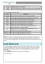
The Time Measurement menu table
Menu
Description
Frequency
Reciprocal of the period of the first cycle in the waveform
Period
Time to take for the first signal cycle to complete in the waveform
Rising
The time taken from lower threshold to upper threshold
Falling
The time taken from upper threshold to lower threshold
+Width
Measured of the first positive pulse in the waveform
-Width
Measured of the first negative pulse in the waveform
+Duty
Positive Duty Cycle = (Positive Pulse Width)/Period x 100%
Measured of the first cycle in waveform
-Duty
Negative Duty Cycle = (Negative Pulse Width)/Period x 100%
Measured of the first cycle in waveform
Delay1->2↑
The delay of rising time between CH1 and CH2
Delay1->2↓
The delay of falling time between CH1 and CH2
Note:
The results of the automatic measurements will be displayed on the bottom of
the screen. Maximum 3 results could be displayed at the same time. When there is no
room, the next new measurement result will make the previous results moving left out of
screen.
Cursor Measurement
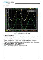
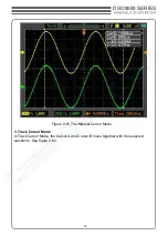
The screen displays two parallel cursors. Move the cursors to make custom voltage
or time measurements of the signal. The values are displayed on the boxes below the
menu. Before using cursors, make sure to set the Signal Source as the channel for
measuring.
Press
CURSOR
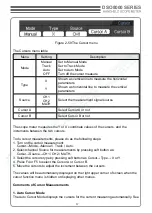
to show the cursor menu as the following:
The Cursor menu


