background image


1.1 Instrument Introduction 

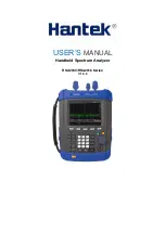
HSA2000  series  spectrum  analyzers  which  are  small,  light  and  cost-effective,  are  portable 
spectrum  analyzers  designed  for  starters.  Configured  with  easy-to-operate  numeric  keyboard, 
high-resolution  color  LCD  display  and  various  remote  communication  interfaces,  they  can  be 
widely used in various fields, such as education, company research and development as well as 
industrial manufacture. 

Main features: 


Frequency Range: 9 kHz to 3.2 GHz (1.6GHz)   


Displayed Average Noise Level (DANL): -135 dBm (Typical)   


Phase Noise: -80 dBc/Hz @ 10 kHz offset   


Total Amplitude Accuracy: <1.5 dB   


Minimum Resolution Bandwidth (RBW): 100 Hz   


VSWR Measurement Kit(Option)   


Standard with Preamplifier   


5.7 inche (600×480 pixels) high-definition display with clear, vivid, and easy-to-use graphical 
interface   


Various interfaces such as LAN, USB Host, USB Device   


Summary of Contents for HSA2030

Page 1: ...USER S MANUAL Handheld Spectrum Analyzer HSA2030 HSA2016 Series V1 0 0...

Page 2: ...ation is all correct and reliable but does not guarantee no mistake in this document Please confirm that the relevant document and specification is the latest valid version before using If needs any h...

Page 3: ...1 1 FREQ 21 3 1 2 SPAN 23 3 1 3 AMPT 24 3 2 Sweep and Function Settings 26 3 2 1 BW 26 3 2 2 Sweep 27 3 2 3 Trace 28 3 3 Marker Measurement 30 3 4 Shortcut Key 33 3 4 1 Auto 33 3 4 2 Preset 34 3 4 3 U...

Page 4: ...ll trace 55 5 6 6 FORMat Subsystem 55 5 7 SENSe Subsystem 56 5 7 1 FREQuency Subsection 56 5 7 2 Span Mode 57 5 7 3 Sweep 57 5 7 4 Detection 57 5 7 5 Bandwidth 58 5 7 6 Average 59 5 7 7 Power 59 5 8 I...

Page 5: ...arth terminal before any inputs or outputs Observe all Terminal Ratings To avoid fire or shock hazard observe all ratings and markers on the instrument and check your manual for more information about...

Page 6: ...HSA2030C 9 kHz to 3 2 GHz 1 6GHz 5M 3G 6000COUNTS HSA2030D 9 kHz to 3 2 GHz 1 6GHz 5M 3G 6000COUNTS YES HSA2030E 9 kHz to 3 2 GHz 1 6GHz 6000COUNTS YES Model No Spectrum Analyzer TG DMM DSO HSA2016A...

Page 7: ...Chapter1 Quick Start Instrument Introduction General Check Preparation...

Page 8: ...us fields such as education company research and development as well as industrial manufacture Main features Frequency Range 9 kHz to 3 2 GHz 1 6GHz Displayed Average Noise Level DANL 135 dBm Typical...

Page 9: ...s are incomplete or damaged please contact the Hantek representative 1 3 To Prepare for Use This chapter introduces the basic process to help you fast start to use the instrument Prepare the instrumen...

Page 10: ...Chapter2 Operating Basics Front Panel Menu Reference Top Panel Side Panel User Interface Menu Operation Parameter Setting...

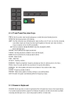
Page 11: ...2 1 1 Menu Reference 1 LCD 2 Menu softkeys menu control keys 3 Charge indicator Only lights up when charging 4 Knob 5 Direction keys 6 Numeric Keyboard 7 Power switch Lighting normal work status 8 Fu...

Page 12: ...lect and control the measurement function MODE Select mode FILE Save files UTILITY Auxiliary function MARKER Read the amplitude frequency and sweep time of a certain point on the trace PEAK Open the p...

Page 13: ...e system will complete the input and insert a default unit for the parameter automatically While in the process of file name editing this key is used to input the character currently selected by the c...

Page 14: ......

Page 15: ......

Page 16: ...urrent X value of the cursor Note that X indicates different physical quantities in different functions Cursor Y Current Y value of the cursor Note that Y indicates different physical quantities in di...

Page 17: ...25 VBW Video bandwidth 26 Spectrum line display area Spectrum line display area 27 Y scale Label of Y scale 28 Manual setting The corresponding parameter is in manual setting mode 2 5 Menu Operation T...

Page 18: ...ues using the numeric keys knob or direction keys This section describes the three methods of parameter setting through an example to set the center frequency to 800 MHz 1 Use the numeric keyboard 1 P...

Page 19: ...Note in the storage function the direction keys can also be used to select the current path or file...

Page 20: ...ic Settings This chapter describes in detail the function keys at the front panel and the associated functions Subjects in this chapter Basic Settings Sweep and Function Settings Marker Measurements S...

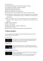
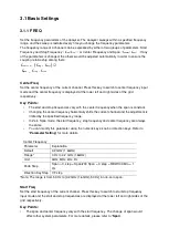
Page 21: ...frequency when the span is constant Changing the center frequency horizontally shifts the current channel and the adjustment is limited by the specified frequency range In Zero Span mode the start fre...

Page 22: ...b or direction keys For more details please refer to Parameter Setting Stop frequency Parameter Explanation Default 3 2 GHz 1 6GHz Range 100 Hz to 3 2 GHz 1 6GHz Unit GHz MHz kHz Hz Knob Step Span 0 s...

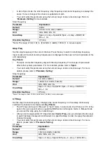
Page 23: ...riation in the span RBW or VBW would cause a change in the sweep time You can modify this parameter using the numeric keys knob or direction keys For more details please refer to Parameter Setting Spa...

Page 24: ...the input attenuation the preamplifier and the maximum mixing level respectively You can modify this parameter using the numeric keys knob or direction keys For more details please refer to Parameter...

Page 25: ...epresents 10 of the reference level and the Scale Div is invalid The unit of Y axis will automatically switch to the default Volts in Lin scale type when the scale type is changed from Log to Lin The...

Page 26: ...eep and Function Settings 3 2 1 BW Set the RBW Resolution Bandwidth VBW Video Bandwidth and detector type parameters of the analyzer RBW Set the desired resolution bandwidth in order to distinguish be...

Page 27: ......

Page 28: ...ons are satisfied Key Points If the instrument is in continuous sweep mode and no measurement function is enabled press this key and the system will enter the single sweep mode and execute specified n...

Page 29: ...cessive sweeps 4 Freeze Stop updating the trace data to observe the trace and read the measurement data This type is generally used by traces loaded from storage devices or remote interface as default...

Page 30: ......

Page 31: ...e mode of zero sweeping width 6 All Off Close all the markers which has been open and its realative function Marker Use current marker value to set other system parameter of equipment like center freq...

Page 32: ......

Page 33: ...ged as peak Parameter Instruction Default 90 dB Range 200 dBm 0 dBm Unit dBm dBm mV uV Knob Step 1 dBm Direction Key Step 1 dBm 3 Peak Search Set the peak which is looked up in peak search is whether...

Page 34: ...is finished Some parameters such as the reference level scale input attenuation and maximum mixing level may be changed during the auto search 3 4 2 Preset Recall the preset setting and restore the a...

Page 35: ...RF Preamp Off BW RBW Auto 1 MHz VBW Auto 1 MHz V R Ratio 1 Sweep Time Auto 690 ms Auto SWT Normal Trace Select Trace 1 Trace Type of Trace 1 Clear Write Avg Times 10 Measure Meas Fctn Off Marker Sele...

Page 36: ...analyzer Default is 100 You can modify this parameter using the numeric keys knob or direction keys Backlight Keeping Set the On Off status of backlight default is Off 15s It can be changed between On...

Page 37: ...se them all 6 Power On Preset Power On Preset includes power on preset type save as user The user can set the power on status according to the requirement Power on The user can select power on status...

Page 38: ...ect using five colors White Red Green Blue and Black Key Test Enter the keyboard test interface Press the function keys at the front panel one by one and observe whether the corresponding key lights I...

Page 39: ......

Page 40: ...lly The level is influenced by input attenuator when signal passes the spectrum analyzer If the signal is very close to the bottom of noise it can differentiate the signal with the noice to reduce the...

Page 41: ...center of screen again Press SPAN 1 MHz 2 Set the attenuation as 20 dB Pay attention that when the attenuation increases the bottom of noice will be more close to signal level Press AMPT Attenuation 2...

Page 42: ...source and amplitude as 1 GHz and 80 dBm Connect the RF OUT port of signal source to the RF IN port of spectrum analyzer and turn on the signal output 3 Set center frequency span and reference level...

Page 43: ...sampling mode 1 Reset spectrum analyzer 2 Set the frequency of signal source and amplitude as 1 GHz and 80 dBm Connect the RF OUT port of signal source to the RF IN port of spectrum analyzer and turn...

Page 44: ...stortion is produced inside the instrument In this case we use a signal output by a function generator as signal source to recognize whether the harmonic distortion component is produced by spectrum a...

Page 45: ...een again Press SPAN 50MHz Press MARKER PEAK 3 Set the attenuation as 0 dB Press AMPT Attenuation 0dB 4 To recognize whether the harmonic distortion component is produced by spectrum analyzer firstly...

Page 46: ...luenced by two factors 1 To increase input attenuation will make signal to noise ratio SNR worse which will cause the reading to be positive 2 The loss of harmonic wave caused by internal circuit of s...

Page 47: ...use SCPI commands to control HSA2000 Series spectrum analyzer by USB LAN or remote interface Contents of this chapter SCPI Brief Introduction General Command CALCulate subsystem DEMOdulation subsyste...

Page 48: ...language of your instrument A HAS Series spectrum analyzer employs SCPI as its programming language SCPI 5 1 2 Command Syntax Command syntax includes standard notations and statement rules Command St...

Page 49: ...A space separates a keyword and a parameter as well as a parameter and a unit 5 1 6 Default unit of parameters The analyzer has the following default units for numeric variables Parameter Default unit...

Page 50: ...OFF Function description This command turns off all markers on all traces Turn on or off COUNT Command format CALCulate MARKer FCOunt STATe OFF ON 0 1 Function description Turn on or off the COUNT fun...

Page 51: ...is no approperate peak been found Marker Peak Right Search Command format CALCulate MARKer MAXimum RIGHt Function description Search a peak which is the nearest on the right of current peak and meets...

Page 52: ...f the continuous peak search Instruction If there is no marker be turned on it turns on Marker 1 automaticly and marks peak 5 4 DEMOdulation Subsystem 5 4 1 AM Demodulation Command format DEMod AM STA...

Page 53: ...ference level Check reference level Parameter specification rel_ampl float data range from 100dBm to 30dBm Return format Return reference level as float data 5 5 3 Trace Y Axis Reference Level Offset...

Page 54: ...e data its format depends on the set of commands FORMat TRACe DATA 5 6 2 Select trace display mode Command format TRACE n MODE WRITe MAXHold MINHold FREEze BLANk TRACE n MODE Function description Set...

Page 55: ......

Page 56: ...unction description Set center frequency Query center frequency Parameter specification freq integral data range 0Hz to 3 2GHz Return format Query and return center frequency as an integer unit is Hz...

Page 57: ...an 5 7 3 Sweep Query span time Command format SENSe SWEep TIME Function description Query span time Return format Query the span time returned as floating point type data Unit is us Set span mode Comm...

Page 58: ...d format SENSe BANDwidth RESolution freq SENSe BANDwidth RESolution Function description Set resolution bandwidth RBW Query resolution bandwidth Parameter specification freq integral data range from 1...

Page 59: ...idth AUTO mode 5 7 6 Average Set average type Command format SENSe BANDwidth AVGType LOGPwr POWEr VOLTage SENSe BANDwidth AVGType Function description Set average type Query average type Parameter spe...

Page 60: ...pre amplifier Return format Query and return the on 1 or off 0 status of the pre amplifier Autoset AUTO Command format SENSe POWer ATUNe Function description Search signals in the full spectrum and ad...

Page 61: ...ance 5 9 TRIGger Subsystem 5 9 1 Set Trigger Type Command format TRIGger SEQuence SOURce IMMdeiate VIDeo EXTernal TRIGger SEQuence SOURce Function description Set trigger type Query trigger type Param...

Page 62: ...mat Query and return trigger level value as the format of floating point data 5 9 4 UNIT Subsystem Select the power unit used for measurement Command format UNIT POWer DBM DBMV DBUV W V UNIT POWer Fun...

Page 63: ...5 10 3 Preset Command format SYSTem PRESet Function description This command makes the relevant setting of spectrum analyzer into preset status...

Page 64: ...wise noted The instrument has been warmed up for 30 minutes The instrument is within the calibration period and a self calibration has been performed Typical value and nominal value are defined as fol...

Page 65: ...layed Average Noise Level normalized to1Hz 9K 1MHz Preamp off 108dBm typical 127dBm 1MHz 10MHz 128dBm typical 146dBm 10MHz 500MHz 142dBm typical 146dBm 500MHz 2 5GHz 1 6GHz 141dBm typical 145dBm 2 5GH...

Page 66: ...ge noise level DANL to 20dB Input attenuator range 0 to 51dB 1dB steps Spurious Response Second Harmonic Distortion SHI 65dBc 50MHz to 3GHz 1 6GHz Mixer level 30dBm attenuator 0dB preamp off 20 30 Thi...

Page 67: ...Weight 2 9kg with battery 2 6kg without battery Size 260m X 220m X 75m Power Input voltage range DC 12 17V maximum 2 8A input 220VAC 15 AC frequency range 40Hz to 60Hz Power consumption Maximum 32W...

Page 68: ...Chapter7 Appendix Appendix A Appendix B...

Page 69: ...choosing HANTEK Please contact us through the following ways should you have any inquiry regarding our products We shall do our best to help you 1 Contact your local HANTEK distributor 2 Contact your...

Page 70: ...es as often as operating conditions require To clean the exterior surface perform the following steps 1 Use a lint free cloth to remove floating dust on the outside of the oscilloscope and probes Take...

Reviews: