MS1000 Control System
Installation Guide
hanwell.com
Page 17 of 30
GD6063-1
7.2
Controller to MS1000 Control Unit - USB Cable Wiring
The CR3/SR2 Controller communicates with the monitoring PC via a USB cable.
7.3
RS485 Wiring from Controller to MS1000 Control Unit
7.3.1
Standalone MS1000 Systems
No RS485 wiring is required for Standalone MS1000 systems as the MS1000 Control Unit’s
Control Board is connected directly to the Output Cards.
The Customer should arrange for the appropriate wiring from the Output Cards to the 3
rd
party
BMS/plant to be controlled via the MS1000 Control Unit.
7.3.2
Monitoring and Control Systems
The MS1000 Control Unit receives control signals from the CR3/SR2 Controller via Hanwell
and Customer supplied, RS485 twisted-pair cables.
The Hanwell supplied cable consists of a 2 metre 4 core cable with a moulded mini-DIN
plug and a free end.
The Customer supplied cable should be to the specifications outlined below in
Table 5 -
Wiring Specifications
.
7.3.2.5
Wiring a Monitoring and Control System
1.
Run the Customer supplied cable from the MS1000 Control Unit’s location back to a
Junction Box, located within 2 meters of the CR3/SR2 Controller’s planned location.
Up to 1000m of cable (from the MS1000 Control Unit to the Junction Box) can be
used without line drivers being required.
2.
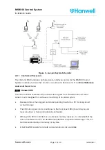
Run the Hanwell supplied cable from the Junction Box to the CR3/SR2 Controller. See
Figure 3 – General System Schematic.
3.
Connect both cables as follows:
i.
Remove the Junction Box’s lid.
ii.
Feed the bare ends of the Hanwell and Customer supplied cables into the
Junction Box through the cable glands and tighten the gland nuts.
4.
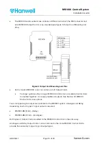
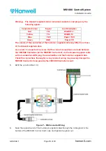
Strip the insulation from the conductors on both cables and connect via the connector
block. See
Figure 7 – MS Connector Wiring
.

