MS1000 Control System
Installation Guide
hanwell.com
Page 21 of 30
GD6063-1
7.4
Wiring the Output Cards
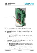
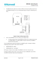
The Outputs from the MS1000 Control System Output Cards, Analogue and Relay, to valves,
heaters, BMS etc via the control wiring should be made to the appropriate Output Card
terminals as specified in Table 6 and Figure 8:
O
UTPUT
CARD
C
HANNEL
OUTPUT PINS
1
2
3
4
R
ELAY
1 & 2
Common
DO NOT USE
Normally Open
(NO)
NC
3 & 4
Common
Normally Open
(NO)
DO NOT USE
NC
A
NALOGUE
1 & 2
I+
Gnd
V+
DO NOT USE
3 & 4
I+
V+
Gnd
DO NOT USE
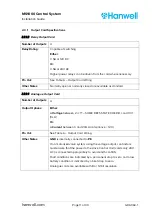
Table 6 – Output Card Wiring
NC = Normally Closed
NO = Normally Open
I+ = Current Output
V+ = Voltage Output
Figure 8 - Output Card Output Pins 1 – 4 for Channels 1 – 4

