41
●
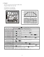
Link Pattern Number (LINK.PT)
●
Recording and Change of Program (Update Confirm)
●
PID Number Select (PID NO. Select)
●
Alarm Number Set (ALM NO. Select)
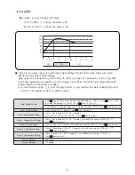
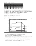
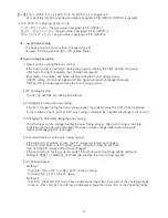
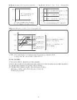
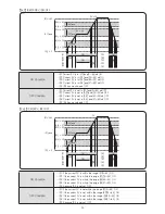
•When the program ends and if you want to link another pattern to that, LINK.PT is to set the parameter.
•Pattern number can be identical to itself. In this case, the pattern infinitely repeats (as same REPEAT=CONTINUE)
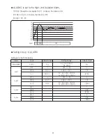
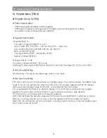
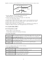
•Program Change
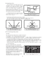
Program can be changed when it is completed or it is running.
If the value is changed during the segment process, the original value will be maintained for the duration of the
segment. After segment is complete, the controller will change to the new value.
If the value of next segment is changed, the controller will immediately change to the new value.
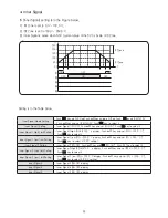
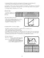
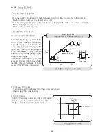
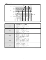
•Segment Number from 1 through 99 (SEG.NO=1~99) :
PID Group Number, Target, Run Time, and Time Signal (TS, TS.ON, and TS.OFF).
NP200 programs four PID groups. Default is PID GROUP-1. All PID control outputs are user programmable
(and each segment can be controlled by corresponding PID)
•LEVEL PID of Control Group
LEVEL=OFF: Each segment is controlled by corresponding PID Group.
LEVEL=ON: All segments are controlled by LEVEL PID.
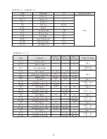
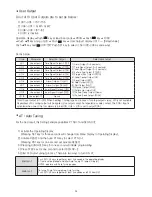
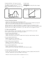
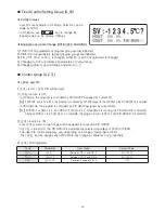
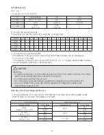
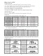
NP200 programs four Alarm Groups (See. G.ALARM).
As shown in Table below, multiple numbers of Alarm Groups can be selected.
If you select ALM. NO 5, 0101 means ALM3 and ALM1 activate.
No
Display
ALM4
ALM3
ALM2
ALM1
0
OFF
X
X
X
X
1
01 : 0001
X
X
X
O
2
02 : 0010
X
X
O
X
3
03 : 0011
X
X
O
O
4
04 : 0100
X
O
X
X
5
05 : 0101
X
O
X
O
6
06 : 0110
X
O
O
X
7
07 : 0111
X
O
O
O
8
08 : 1000
O
X
X
X
9
09 : 1001
O
X
X
O
10
10 : 1010
O
X
O
X
11
11 : 1011
O
X
O
O
12
12 : 1100
O
O
X
X
13
13 : 1101
O
O
X
O
14
14 : 1110
O
O
O
X
15
15 : 1111
O
O
O
O
Example)
05 : 0 1 0 1
ALM 4 (No operate)
ALM 3 (Operate)
ALM 2 (No operate)
ALM 1 (Operate)
Summary of Contents for NP200
Page 2: ......

