12
8
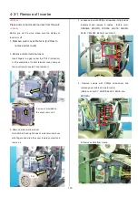
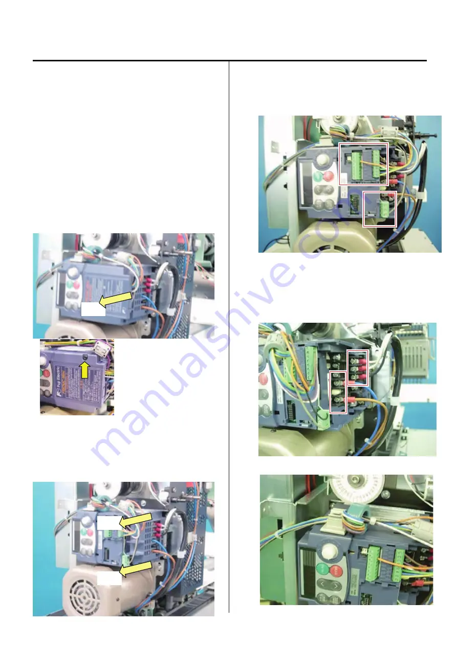
4-3-1 Remove of Inverter
<Notice>
Please disconnect machine inlet from the wall.
<Check>
Before you start to work, make sure the display of
inverter is off.
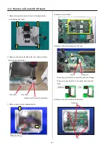
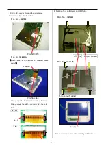
1. Remove outer cover. Refer to [2-2 How to
remove outer cover].
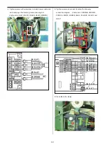
2.
Remove control terminal cover.
Insert fingers in a gap (under the “PULL” indication)
on the underside of control terminal cover, and pull
the cover toward yourself and remove it.
If screw is provided on
the cover, remove it.
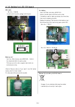
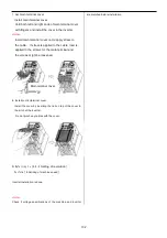
3. Remove main terminal cover
Hold both left and right ends of main terminal cover
with fingers and slide the cover toward yourself and
remove it.
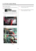
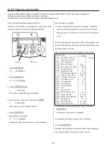
4. Loosen screw with Phillips screwdriver for precision
instrument and remove 9 cables. (Cable color:
ORANGE, BROWN, PURPLE, WHITE, GREEN,
BLUE, YELLOW, BLACK, and GLAY)
5. Remove screws with Phillips screwdriver and
remove power cable and motor cable.
(Cable color: GLAY, WHITE BLACK, BLUE, and
BROWN)
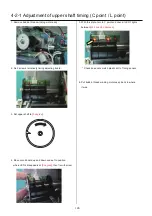
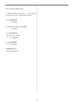
6. Remove cable from clamp.
Pull
Pull
Pull
Summary of Contents for HCS2-1201-30
Page 1: ...Maintenance Manual for Embroidery Machine HCS2 1201 30 Version 2 3 HappyJapan Inc...
Page 154: ...153 5 1 1 Electrical connection diagram except for Rev A...
Page 155: ...154 5 1 1 Electrical connection diagram except for Rev A...
Page 156: ...155 5 1 2 List of electrical connection diagrams except for Rev A...
Page 157: ...156 5 1 3 Electrical connection diagram for Rev A...
Page 158: ...157 5 1 3 Electrical connection diagram for Rev A...
Page 159: ...158 5 1 4 List of electrical connection diagrams for Rev A...
Page 160: ...159 5 2 1 Connection of inverter 100V Inverter set...
Page 161: ...160 5 2 2 Connection of inverter 200V Inverter set...
Page 165: ...160c HCD8116 TP switch board ass y 6 5 265 2 1 6 7 257...

