1
85
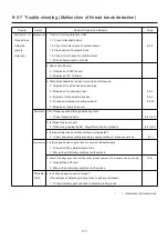
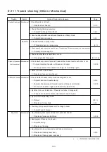
No. message Error measure page
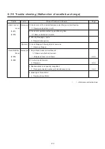
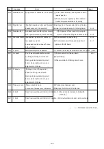
130 Disk error Unable to communicate continuously (1)Turn off power source once and turn it on again.
with memory media. (2)Memory media reading processor may defective.
Replace the LCD-CE board. 4-1-1
131 Device no ready Memory media is not set. Check if memory media is properly set. ( 5-5 )
133 Bad disk Improper or faulty memory media. (1)Memory media might be not eadable with ( 5-5)
the machine. Prepare readable memory
media for the machine.
(2)Memory media might be defective.
Prepare another memory media
which is not defective.
(3)Initialize (FAT 32) the memory media
if it is not initialized.
141 Not found name Designated pattern is not found. Memory media might be not readable with ( 5-5 )
the machine.
Prepare readable memory media for the machine.
142 Disk full Memory media is full to capacity. Clear unnecessary patterns or use a different
memory media.
143 Multi name Another pattern with same name has Change name, use a different memory media,
been detected while attempting to or overwrite existing pattern.
write to memory media.
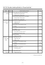
190 Cut blade Thread cut knife is not at stop position. (1)Restore the moving knife to stop position. ( 24-5 )
(2) Check dirt of trim sensor or position of slit.
(3)Modify the adjustment if the problem repeats.
(4) Adjust sensor position.
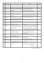
191 Cut Sensor
Thread cutting device did not
(1) Press the [CUT] button 2~3 times.
move correctly.
(2) Check if thread is twined around the moving
knife
.
(3) If photo sensor is stained, clean.
(4) Replace the photo sensor board.
193 Catcher Thread catch hook is not in its (1)Check if mistake is found in thread cut. ( 24-6 )
stop position. If found, cut thread and move thread catch
hook to proper position.
(2)Adjust and correct trouble that hinders motion
of thread catch hook.
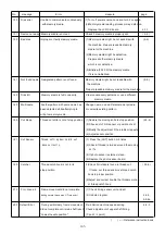
215 Frm. drive err Frame movement did not complete
.
(1) Check timing sensor unit and slit.
during normal movement. (Time over)
(2) Update program 4-4-3,
4-4-4a
255 Default Error During embroidery, frame movement Re-initialize machine speed setting. 4-4-5
did not complete until main shaft reach Check adjustment of upper shaft timing.
“Lowest needle position". (C point / L point)
( ) ----- Reference instruction book
Summary of Contents for HCS2-1201-30
Page 1: ...Maintenance Manual for Embroidery Machine HCS2 1201 30 Version 2 3 HappyJapan Inc...
Page 154: ...153 5 1 1 Electrical connection diagram except for Rev A...
Page 155: ...154 5 1 1 Electrical connection diagram except for Rev A...
Page 156: ...155 5 1 2 List of electrical connection diagrams except for Rev A...
Page 157: ...156 5 1 3 Electrical connection diagram for Rev A...
Page 158: ...157 5 1 3 Electrical connection diagram for Rev A...
Page 159: ...158 5 1 4 List of electrical connection diagrams for Rev A...
Page 160: ...159 5 2 1 Connection of inverter 100V Inverter set...
Page 161: ...160 5 2 2 Connection of inverter 200V Inverter set...
Page 165: ...160c HCD8116 TP switch board ass y 6 5 265 2 1 6 7 257...

