

29
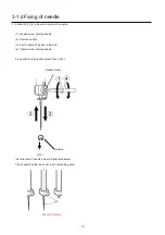
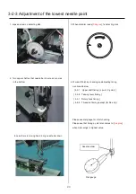
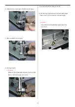
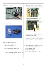
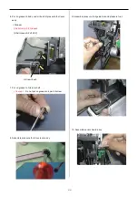
3-2-3 Adjustment of the lowest needle point
1. Loosen screw on detecting disk.
2. Turn upper shaft so that needle bar driver ass’y comes
in the bottom.
In case there is moving head, bring needle bar down.
3. When dial disc reads [
0 degree
], fix detecting disk.
4. Work will finish by checking and adjusting timing
mentioned below.
[ 4-2-1 Upper shaft timing (L point, C point) ]
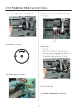
[ 3-2-8 Take-up lever timing ]
[ 3-5-1 Rotary hook timing ]
[ 3-6-5 Thread cut timing (except (for Rev.A) ))
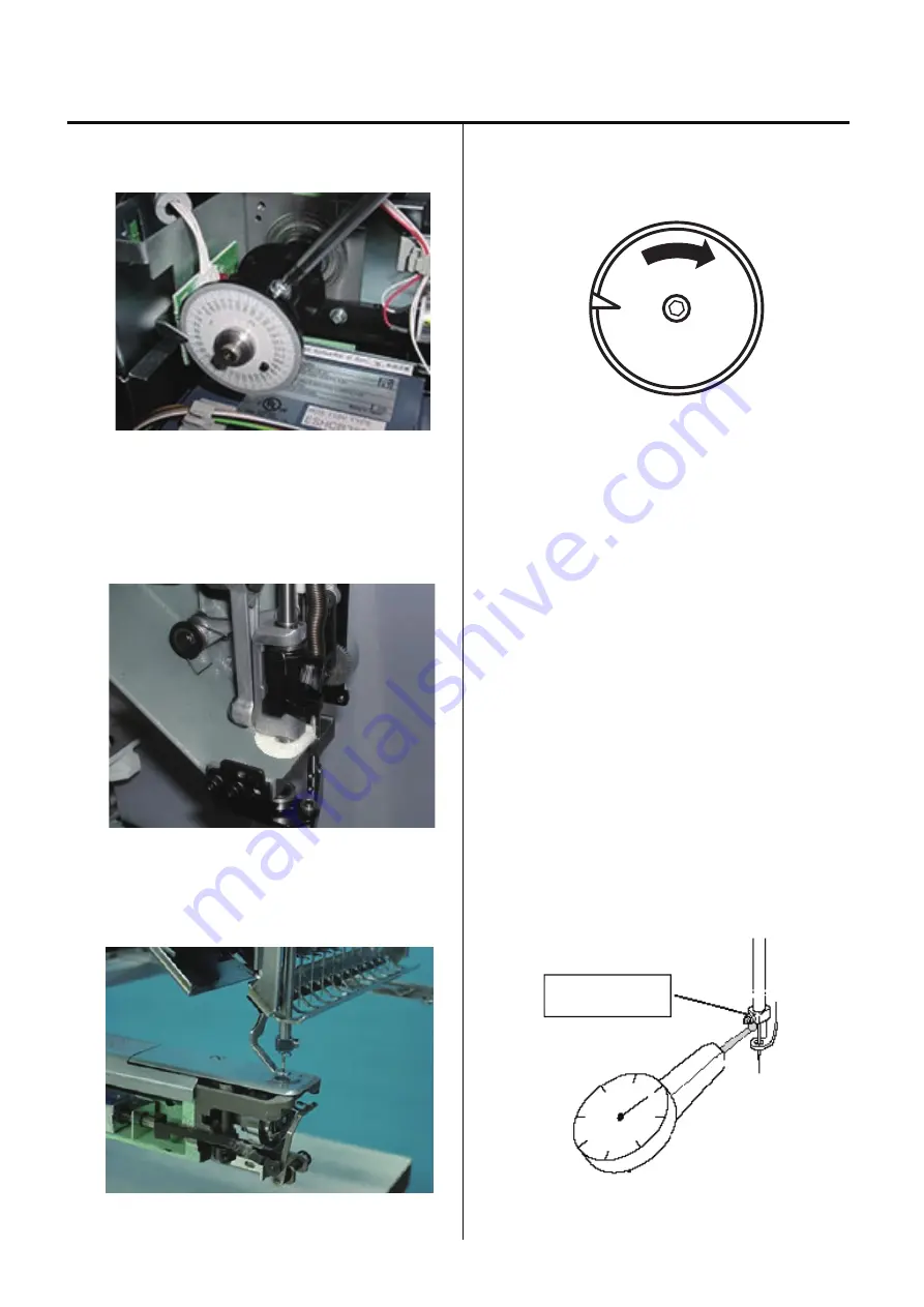
Please use dial gauge for strict checking.
Please see that timing on dial disc comes to [
0 degree
]
when dial swings in highest value.
Dial-gauge
Needle holder
Summary of Contents for HCS2-1201-30
Page 1: ...Maintenance Manual for Embroidery Machine HCS2 1201 30 Version 2 3 HappyJapan Inc...
Page 154: ...153 5 1 1 Electrical connection diagram except for Rev A...
Page 155: ...154 5 1 1 Electrical connection diagram except for Rev A...
Page 156: ...155 5 1 2 List of electrical connection diagrams except for Rev A...
Page 157: ...156 5 1 3 Electrical connection diagram for Rev A...
Page 158: ...157 5 1 3 Electrical connection diagram for Rev A...
Page 159: ...158 5 1 4 List of electrical connection diagrams for Rev A...
Page 160: ...159 5 2 1 Connection of inverter 100V Inverter set...
Page 161: ...160 5 2 2 Connection of inverter 200V Inverter set...
Page 165: ...160c HCD8116 TP switch board ass y 6 5 265 2 1 6 7 257...