
39
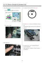
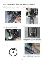
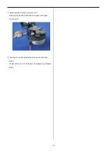
3-2-10 Check of height of pressure foot
1. Bring pressure foot down. (Either way mentioned below)
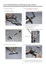
(1)press
P_FOOT key on control box.
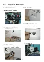
(2)Turn gear with finger.
2. Bring needle down.
3. Turn upper shaft and set dial disc to [
0 degree
].
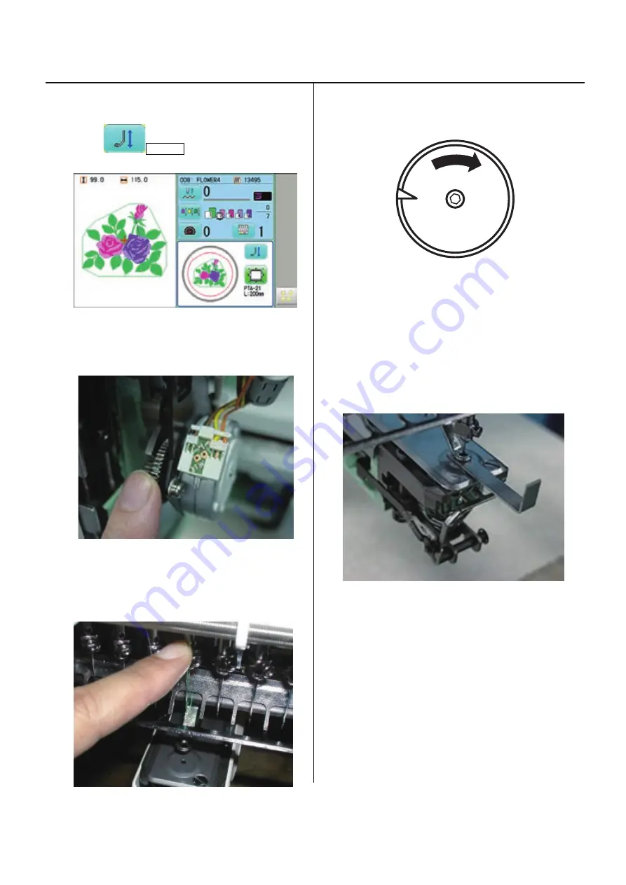
4. Insert [
Gauge I.2mm
] between needle plate and pressure
foot.
No gap between gauge and pressure foot or needle plate,
will be OK.
5. If wrong space (not 1.2mm), please adjust height of
pressure foot guide bar.
Please refer to [3-2-12 Adjustment of height of pressure
foot guide bar ].
Summary of Contents for HCS2-1201-30
Page 1: ...Maintenance Manual for Embroidery Machine HCS2 1201 30 Version 2 3 HappyJapan Inc...
Page 154: ...153 5 1 1 Electrical connection diagram except for Rev A...
Page 155: ...154 5 1 1 Electrical connection diagram except for Rev A...
Page 156: ...155 5 1 2 List of electrical connection diagrams except for Rev A...
Page 157: ...156 5 1 3 Electrical connection diagram for Rev A...
Page 158: ...157 5 1 3 Electrical connection diagram for Rev A...
Page 159: ...158 5 1 4 List of electrical connection diagrams for Rev A...
Page 160: ...159 5 2 1 Connection of inverter 100V Inverter set...
Page 161: ...160 5 2 2 Connection of inverter 200V Inverter set...
Page 165: ...160c HCD8116 TP switch board ass y 6 5 265 2 1 6 7 257...