5
9
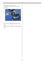
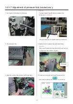
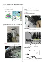
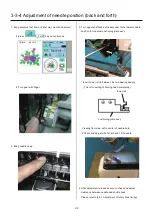
4. Turn the drive shaft B screw for manual operation,
and make it the 1st needle.
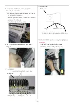
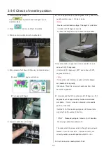
* When a moving head is caught on the way and does not
carry out horizontal movement.
The screw tightened tentatively in "the work procedure 1"
has come out from LM guide.
A screw from LM guide. Please fasten.
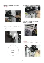
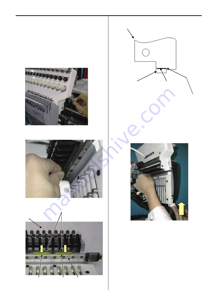
5. Put in SIMM [0.05mm] between a moving head and
LM guide.
<View of behind>
To puts in (central position between screws)
Moving head
SIMM (Middle) SIMM (Left) LM guide
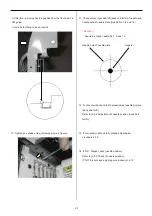
<Veiw of left side>
Moving head
LM guide SIMM (Three places)
Position (it puts in to the back) which SIMM puts in.
* Don't put in SIMM but push up a moving head lightly a case.
<important>
Please do not lower LM guide by any means.
There is a possibility that LM guide may bend.
Summary of Contents for HCS2-1201-30
Page 1: ...Maintenance Manual for Embroidery Machine HCS2 1201 30 Version 2 3 HappyJapan Inc...
Page 154: ...153 5 1 1 Electrical connection diagram except for Rev A...
Page 155: ...154 5 1 1 Electrical connection diagram except for Rev A...
Page 156: ...155 5 1 2 List of electrical connection diagrams except for Rev A...
Page 157: ...156 5 1 3 Electrical connection diagram for Rev A...
Page 158: ...157 5 1 3 Electrical connection diagram for Rev A...
Page 159: ...158 5 1 4 List of electrical connection diagrams for Rev A...
Page 160: ...159 5 2 1 Connection of inverter 100V Inverter set...
Page 161: ...160 5 2 2 Connection of inverter 200V Inverter set...
Page 165: ...160c HCD8116 TP switch board ass y 6 5 265 2 1 6 7 257...

