

100
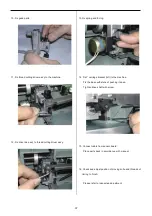
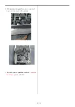
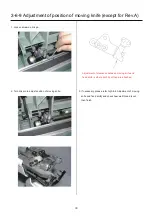
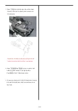
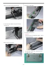
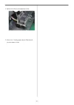
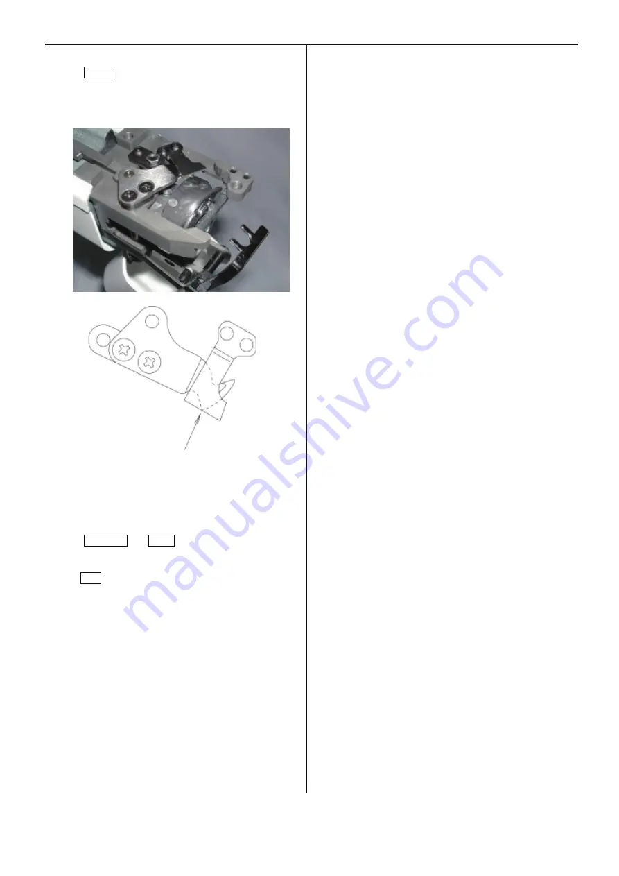
7. Press Origin, then the Moving knife will be closed.
Please confirm that the Moving knife is located as
drawing below.
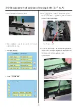
Adjustment of clearance between moving knife and
fixed knife is where both tip of then are attached.
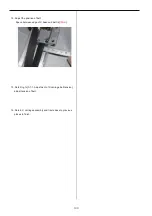
8. Press Separate and Origin by turns to confirm that t
he Moving knife is closed in the right position.
Press ESC to finish
「
Maintenace mode
」
.
9. If necessary, please refer to [3-6-8 Adjustment of moving
knife and fixed knife] and check how well thread is cut,
then finish.
Summary of Contents for HCS2-1201-30
Page 1: ...Maintenance Manual for Embroidery Machine HCS2 1201 30 Version 2 3 HappyJapan Inc...
Page 154: ...153 5 1 1 Electrical connection diagram except for Rev A...
Page 155: ...154 5 1 1 Electrical connection diagram except for Rev A...
Page 156: ...155 5 1 2 List of electrical connection diagrams except for Rev A...
Page 157: ...156 5 1 3 Electrical connection diagram for Rev A...
Page 158: ...157 5 1 3 Electrical connection diagram for Rev A...
Page 159: ...158 5 1 4 List of electrical connection diagrams for Rev A...
Page 160: ...159 5 2 1 Connection of inverter 100V Inverter set...
Page 161: ...160 5 2 2 Connection of inverter 200V Inverter set...
Page 165: ...160c HCD8116 TP switch board ass y 6 5 265 2 1 6 7 257...


