112
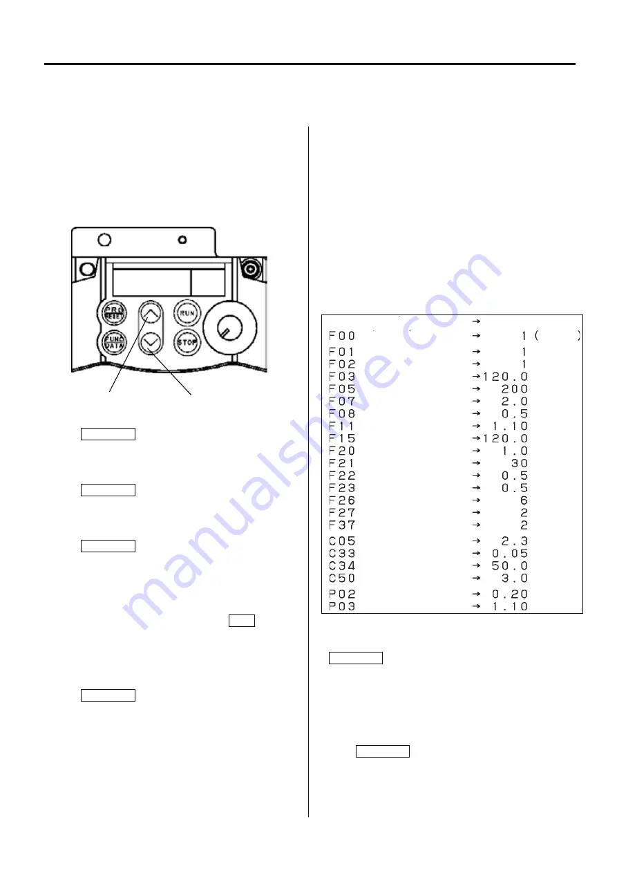
Prohibition of change
Frequency set mode
Drive / Operation
Maxmum frequency
Base frequency volteage
Acceleration time 1
Deceleration time1
Motor thermal protection
Upper limit freq. limter
DC brake. starting freq.
DC braking current
DC braking time
Start frequency
Carrier frequency
Tone
Load selection
Multi stage frequency 1
Analog input filter
Analog input adjustment
Bias frequency
Motor capacity
Motor rated current
Code Function
Setting
Protect
6-2-1 How to set inverter
In case of spare parts supply, parameter is preset. Please contact HAPPY, when you need to change it.
Parameter cannot be set while machine is running .
Pay attention to electric wires as setting is done with power is on.
How to release the setting change prohibition
Release the prohibition by following the procedures below
since parameter is set as setting change prohibition.
1. Press PRG/RESET.
[ I.F _ _ ] is displayed.
2. Press FUNC/DATA.
[ F 0 0 ] is displayed.
3. Press FUNC/DATA again.
[ 1 ] is blinking.
(This means setting change is prohibited.)
4. Press Up key or Down key while pressing STOP.
[ 0 ] is blinking.
(This means you can change settings.)
5. Press FUNC/DATA.
After [SAVE] is indicated,
[ F 0 1 ] is displayed.
By above process, you will be able to set parameters.
Next, change each setting.
6. Press Up key and function code is displayed. Select the
function code whose parameter you would like to change.
(Press Down key and the function code returns to the
previous code.)
The following table shows function codes, setting details, and
factory default setting. Functions other than described below
are initial setting of inverter.
Refer to the next clause for the method of initial setting.
7. Select the code you would like to change and press
FUNK/DATA.
Parameter of the function is displayed.
8. Change parameter by pressing Up or Down key.
9.
Press
FUNK/DATA.
After [SAVE] is displayed, the next function code is displayed.
This means change of the function code is made.
Up key
Down key
Summary of Contents for HCD2-1501-40
Page 1: ...Maintenance Manual for Embroidery Machine HCD2 1501 40 Version 2 3 HappyJapan Inc ...
Page 10: ...10 HSA90311 Shell alvania EP Grease2 100g Page 31 33 36 M0404342 Needle height gauge Page 52 ...
Page 150: ...143 10 1 Electrical connection diagram before Rev A for LCD CE board 1 3 ...
Page 151: ...144 10 1 Electrical connection diagram before Rev A for LCD CE board 2 3 ...
Page 152: ...145 10 1 Electrical connection diagram before Rev A for LCD CE board 3 3 ...
Page 153: ...146 10 2 Electrical connection diagram before Rev A for LCD CE U LCD CE MX board 1 4 ...
Page 154: ...147 10 2 Electrical connection diagram before Rev A for LCD CE U LCD CE MX board 2 4 ...
Page 155: ...148 10 2 Electrical connection diagram before Rev A for LCD CE U LCD CE MX board 3 4 ...
Page 156: ...149 10 2 Electrical connection diagram before Rev A for LCD CE U LCD CE MX board 4 4 ...
Page 157: ...149a 10 2a Electrical connection diagram Rev A 1 4 ...
Page 158: ...149b 10 2a Electrical connection diagram Rev A 2 4 ...
Page 159: ...149c 10 2a Electrical connection diagram Rev A 3 4 ...
Page 160: ...149d 10 2a Electrical connection diagram Rev A 4 4 ...
Page 161: ...150 10 3 Connection of inverter Inverter set Inverter set ...
Page 165: ...153 HCD8116 TP SW Circuit Board Ass y HCD8124 TC8 7 Circuit Board Ass y Rev A ...
Page 166: ...154 HCD8119 y ...


