115
7
Program update procedure
* The sequence of procedures of program update is described below..
If you need more details, please refer to each manual.
1. Insert the updated program downloaded USB memory to the USB port of the machine
with its power turned “OFF”.
Press NEXT while pressing START/STOP button of the control box at the screen after
the machine is booted.
2. Enter maintenance mode and update machine program and main program from the menu.
3. [Replacement of CONT-D2 board]
Register frame position in Maintenance Mode.
4. Press [MENU] button and select [System] in menu of [OTHER] for initialization of system.
5. Press [MENU] button and select [Speed] in menu of [OTHER] for automatic speed setting.
6. [Replacement of LCD-CE board]
Calender setting
7. end of process
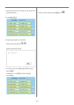
7-2 Update Machine
program
7-3 Update Main program
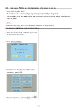
7-3 Initialize machine
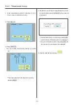
8-6 Position Registration
of coordinates for
positioning sensor
Summary of Contents for HCD2-1501-40
Page 1: ...Maintenance Manual for Embroidery Machine HCD2 1501 40 Version 2 3 HappyJapan Inc ...
Page 10: ...10 HSA90311 Shell alvania EP Grease2 100g Page 31 33 36 M0404342 Needle height gauge Page 52 ...
Page 150: ...143 10 1 Electrical connection diagram before Rev A for LCD CE board 1 3 ...
Page 151: ...144 10 1 Electrical connection diagram before Rev A for LCD CE board 2 3 ...
Page 152: ...145 10 1 Electrical connection diagram before Rev A for LCD CE board 3 3 ...
Page 153: ...146 10 2 Electrical connection diagram before Rev A for LCD CE U LCD CE MX board 1 4 ...
Page 154: ...147 10 2 Electrical connection diagram before Rev A for LCD CE U LCD CE MX board 2 4 ...
Page 155: ...148 10 2 Electrical connection diagram before Rev A for LCD CE U LCD CE MX board 3 4 ...
Page 156: ...149 10 2 Electrical connection diagram before Rev A for LCD CE U LCD CE MX board 4 4 ...
Page 157: ...149a 10 2a Electrical connection diagram Rev A 1 4 ...
Page 158: ...149b 10 2a Electrical connection diagram Rev A 2 4 ...
Page 159: ...149c 10 2a Electrical connection diagram Rev A 3 4 ...
Page 160: ...149d 10 2a Electrical connection diagram Rev A 4 4 ...
Page 161: ...150 10 3 Connection of inverter Inverter set Inverter set ...
Page 165: ...153 HCD8116 TP SW Circuit Board Ass y HCD8124 TC8 7 Circuit Board Ass y Rev A ...
Page 166: ...154 HCD8119 y ...


